


Controller Installation
Installation
3-4
820-0332
2.
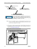
Lift the regulator adjustment knob and turn counterclockwise until it stops to
shut off the regulator air output. Do this on both regulators.
3.
Install 1/4 O.D. x 0.170 I.D. polyethylene tubing (not supplied) to the main air
source and then connect to the input fitting on the regulators. (The left side
when facing the gauge.)
4.
Connect the
regulator-to-pneumatic controller air hoses
(P/N 210-2001
supplied) to the
output fittings
on the regulators. (The right-side fittings when
facing the gauge.)
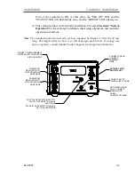
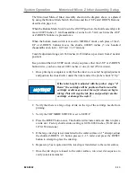
5.
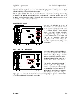
Plug one of the
regulator-to-controller air hoses
into the
AIR IN port labeled
“SHUTTLE” on the rear of controller.
6.
Plug the 2
nd
regulator-to-controller air hose
into the
AIR IN port labeled
“CART” on the rear of controller.
Note:
The air hose connectors are spring locked. If the air hose connectors do not insert
easily, make sure the spring lock is in the open position by pushing the metal snap-
lock down until it clicks.
7.
Turn on the main air and adjust the regulator until it reads 80
±
5 PSI on both
regulator dials. To make regulator adjustments, pull up on the knob on the top
of the regulator to unlock, then rotate the knob clockwise to increase or
counterclockwise to decrease. Push down on the knob after adjustment to lock
it into position.
8.
Check all connections for air leaks. If required, turn off the main air and make
necessary adjustments / repairs.
9.
Install the
cable/connector cable
to the inker port on the prober and the
"PROBER
"
connector on the rear of the controller unit.
10.
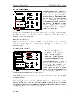
Move the toggle switch on front of the controller to "RUN" (mid) position.
11.
Connect the fitting on the controller-to-shuttle air hose into the pneumatic
connection on the rear of the pneumatic controller labeled "SHUTTLE". (The
large port in the top left hand corner on the controller back panel: NOT the port
with the same name in the “Air In” section below the large port.)
12.
Motorized Micro-Z inker only:
Route the cable and connector from the inker
to the mating jack on the rear of the controller labeled "MOTOR" and connect.
If you are connecting a Manual Micro-Z inker, go to step 13 and connect the
power supply.
13.
Install the
AC power cord
into the back of the power supply. Connect the power
supply cord to the 24V-.84A socket on the back of the controller. Plug the AC
power cord into a 100-240 VAC supply outlet. Turn the ON/OFF switch on the
Summary of Contents for 340-7110
Page 10: ...1 2 820 0332 This page is intentionally left blank...
Page 18: ...Controller Installation Installation 3 6 820 0332 This page is intentionally left blank...
Page 34: ...Cartridge Priming Tips System Operation 820 0332 4 16 This page is intentionally left blank...
Page 40: ...Ink Removal Information Ink 820 0332 5 6 This page is intentionally left blank...


