Installation
Controller Installation
820-0332
3-5
front of the controller to ON. At this point, the "INK ON" LED and the
"STATUS" LED will flash faintly once, and the “POWER” LED will stay on.
14.
This completes Inker and Controller installation. Proceed to
Section 4 “System
Operation”
for ink cartridge installation, inker setup, alignment, and controller
operation instructions.
Note
: The standard controller-to-shuttle air hose supplied by Xandex is 3 feet (91.44 cm)
long. The length of this air hose is a critical design specification. If a longer air
hose is required, consult Xandex Product Support for mitigation information.
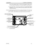
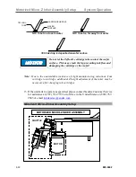
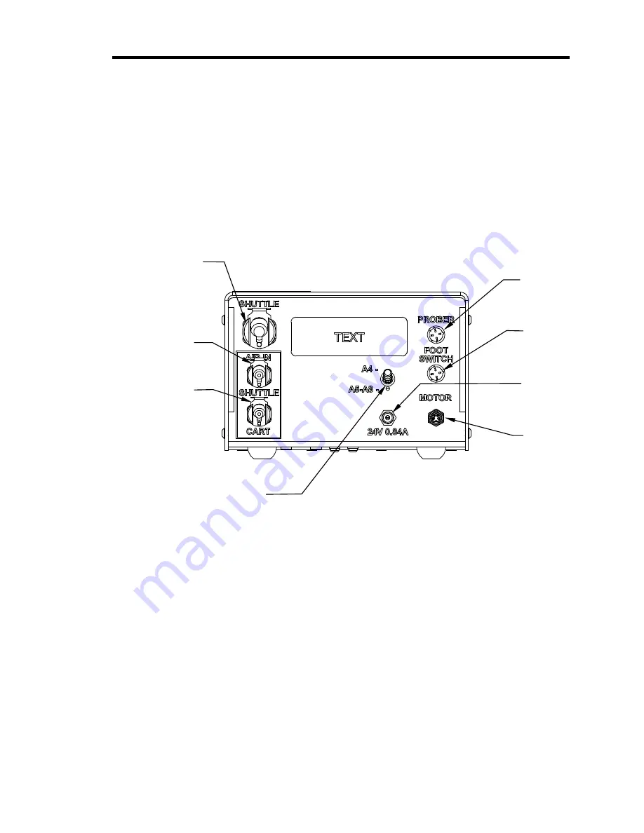
CONNECT INKER ASSEMBLY
CONTROLLER -TO-SHUTTLE
AIR HOSE HERE
CONNECT CABLE/
CONNECT
ASSEMBLY
HERE
CONNECT #1
REGULATOR-TO-
CONTROLLER AIR
HOSE HERE
CONNECT 24V DC
POWER SUPPLY HERE
OPTIONAL FOOT
SWITCH PORT
MOTORIZED INKER
ONLY: CONNECT
INKER MOTOR
CABLE
CONNECTOR HERE
CONNECT #2
REGULATOR-TO-
CONTROLLER AIR
HOSE HERE
PUFF PULSE SELECTOR SWITCH:
PLACE IN A4 MODE TO USE A4
CARTRIDGE
PLACE IN A5-A8 MODE TO USE A5,
A6, OR A8 CARTRIDGE
Summary of Contents for 340-7110
Page 10: ...1 2 820 0332 This page is intentionally left blank...
Page 18: ...Controller Installation Installation 3 6 820 0332 This page is intentionally left blank...
Page 34: ...Cartridge Priming Tips System Operation 820 0332 4 16 This page is intentionally left blank...
Page 40: ...Ink Removal Information Ink 820 0332 5 6 This page is intentionally left blank...


