


System Operation
Motorized Micro-Z Inker Assembly Setup
820-0332
4-13
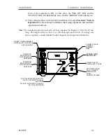
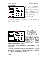
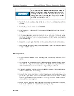
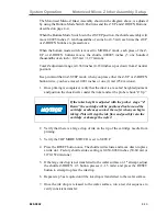
The Motorized Micro-Z Inker Assembly shown in the diagram above, is adjusted
by using the Bottom Mode Switch Positions and the Z UP and Z DOWN Buttons:
described on page 4-4.
When the Bottom Mode Switch is in the Z-STEP position, the shuttle assembly will
move 0.0005 inches (5 ten thousandths of an inch or 0.5 mil) each time the Z-UP
or Z-DOWN buttons are pressed once.
When the bottom mode switch is moved to MICRO-Z mode, each press of the Z-
UP or Z-DOWN buttons moves the shuttle 0.00005 inches (5 one hundred
thousandths of an inch = 0.05 mil = 1.27 micron).
Total Z adjustment range is 0.360 inches (0.180 inches up or down from Z neutral
position).
Keep in mind that in Z-STEP mode, when you press either the Z-UP or Z-DOWN
button twice, you have moved 0.001 inches or one (1) mil (25.4 microns).
1.
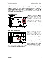
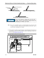
Once priming is completed, verify that the inker is at a safe Z height adjustment
and position the chuck/wafer under the inker and set the prober chuck “Z Up”.
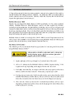
If the inker height is adjusted with the prober stage "Z
Down" the cartridge will be positioned too low and the
cartridge needle may contact the wafer when you begin
inking. This will stop the ink flow and possibly ruin the
cartridge or damage the wafer!
2.
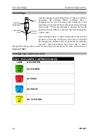
Verify that there is a large drop of ink on the tip of the cartridge needle from
priming.
3.
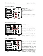
Verify the TOP MODE SWITCH is set to SETUP.
4.
Press the RESET button once. The shuttle will actuate and move down to place
an ink dot. Factory shuttle stroke setting is 0.050-0.060 inches (50-60 mil or
1270-1524 microns)
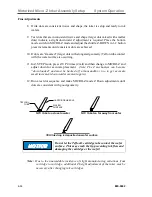
5.
If the large ink drop is not transferred to the wafer surface on 1
st
attempt, adjust
the shuttle Z-DOWN 2-3 button presses (1-1.5 mils) and press the RESET
button to attempt to place the ink drop.
6.
Repeat step 5 as required until the ink drop is transferred to the wafer surface.
7.
Once the ink drop is released to the wafer surface, run a test dot sequence to
verify consistent transfer.
Summary of Contents for 340-7110
Page 10: ...1 2 820 0332 This page is intentionally left blank...
Page 18: ...Controller Installation Installation 3 6 820 0332 This page is intentionally left blank...
Page 34: ...Cartridge Priming Tips System Operation 820 0332 4 16 This page is intentionally left blank...
Page 40: ...Ink Removal Information Ink 820 0332 5 6 This page is intentionally left blank...


