System Specifications
System Drawings
820-0332
7-7
System Drawings
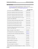
The Inker Assembly Dimensional Drawings are available via link from
The remaining drawings in the list below are available on
request, in Adobe PDF format, from
Description
Drawing Number
X7111 Micro-Z Manual Pneumatic Inker Set (EG)
340-7110-01
X7112 Micro-Z Manual Pneumatic Inker Set (KLA)
340-7110-02
X4113 Micro-Z Manual Pneumatic Inker Set (TSK)
340-7110-03
X7114 Micro-Z Manual Pneumatic Inker Set (TEL)
340-7110-04
X7115 Micro-Z Manual Pneumatic Inker Set (Add your
connector to ink signal cable)
340-7110-05
X7121 Micro-Z Motorized Pneumatic Inker Set (EG)
340-7120-01
X7122 Motorized Z Pneumatic Inker Set (KLA)
340-7120-02
X7123 Motorized Z Pneumatic Inker Set (TSK)
340-7120-03
X7124 Motorized Z Pneumatic Inker Set (TEL)
340-7120-04
X7125 Micro-Z Manual Pneumatic Inker Set (Add your
connector to ink signal cable)
340-7120-05
Harness, Pneumatic Controller, Micro-Z
240-0526
X7110 Manual Micro-Z Pneumatic Inker Dimensions
X7210 Motorized Micro-Z Pneumatic Inker Dimensions
24 VDC Power Supply
220-0078
Pneumatic Controller Assy
350-0027
Controller Logic Board PC Assy
250-1226
Micro-Z Schematic, Logic Board
950-1226
PCA, Daughter Card, Micro-Z
250-1240
Schematic, Daughter Card, Micro-Z
950-1240
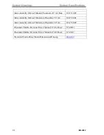
Inker Assembly, Micro-Z Manual, Pneumatic 36” Air Hose
320-7110-01
Summary of Contents for 340-7110
Page 10: ...1 2 820 0332 This page is intentionally left blank...
Page 18: ...Controller Installation Installation 3 6 820 0332 This page is intentionally left blank...
Page 34: ...Cartridge Priming Tips System Operation 820 0332 4 16 This page is intentionally left blank...
Page 40: ...Ink Removal Information Ink 820 0332 5 6 This page is intentionally left blank...

