20
Smart Pad
3
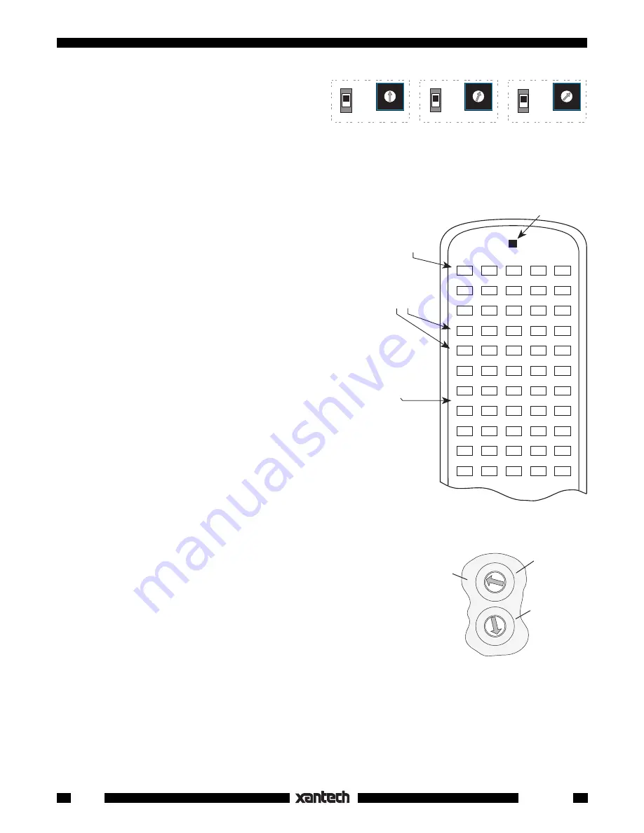
Fig. 22
RC68+ With Overlay
I
for
Relay Mute Programming.
(RC68 works also, but the
I
ON/TOG
OFF
0
ON/TOG
OFF
1
ON/TOG
OFF
2
ON/TOG
OFF
3
ON/TOG
OFF
4
ON/TOG
OFF
5
ON/TOG
OFF
6
ON/TOG
OFF
7
ON/TOG
OFF
8
ON/TOG
OFF
9
ON/TOG
OFF
A
ON/TOG
OFF
B
ON/TOG
OFF
C
ON/TOG
OFF
D
ON/TOG
OFF
E
ON/TOG
OFF
F
I
#
0
ON/ TOG Button
with Code Group
FA
initiates Relay Mute
Coding Procedure.
(Step 5)
These numbers,
0~F
, represent
16 addresses
0~F
on SmartPad3's.
Use
I
Overlay
There is an
ON
/
TOG
and
an
OFF
IR command
assigned for
each address.
Code Group
D8
(default).
RC68
(rear
panel)
0 1 2
3
4
5
6
78
9A
B
C
D
E
F
0 1 2
3
4
5
6
78
9A
B
C
D
E
F
1st Digit
(Left on
RC68+,
Upper on
RC68)
2nd Digit
(Right on
RC68+,
Lower on
RC68)
Fig. 23
D8
Default
Code Group
Setting for
SmartPad
3
7. Within 3 seconds, press the button on the
SmartPad
3
where you want Relay
Mute ON
(i.e.
a MUTE ON button. See
Fig. 24
). The active
Source
button LED
will flash twice
to confirm
your action.
8. Again, within 3 seconds, press the button on the
SmartPad
3
where you want Relay
Mute OFF
(i.e. a MUTE OFF button). The active
Source
button LED
will flash twice
to confirm your
action followed by
four flashes
to indicate the
end of Relay Mute programming for
Address 0
.
The 1st SmartPad
3
has now been coded to respond to
the
MUTE
ON
and
MUTE OFF
buttons (pair) you
selected on the SmartPad
3
.
It will
also
respond, over the IR network, to the #
0 ON/
TOG
and
OFF
IR commands from the RC68+ (or
RC68) set to the default Code Group
D8
. Refer to
Figs. 22
&
23
.
9. Test the IR commands by setting the rear
switches on the RC68 to
D8
(the factory default
Code Group setting for the SmartPad
3
).
10. Pressing the #
0 ON/TOG
IR command on the
RC68 should cause the Relay to
MUTE ON
(if
OFF). Pressing the #
0 OFF
button should cause
the Relay to
MUTE OFF
(if ON). Refer to
Fig. 22
.
Programming the remaining SmartPad
3
's
Each remaining keypad will need to respond to unique
muting commands, otherwise muting one room on the
IR network with the RC68 IR commands, will mute all
the rest as well.
Since any PM110 can store unique coding for up to 16
addresses, we will use the 1st keypad to program
codes for the rest, as follows:
11. On the 1st keypad (PM110), change the
NET-
WORK ADDRESS
switch to match an address
of the next keypad in the system (i.e.,
1
) then
press
RESTORE
on the 1st keypad.
12. Repeat steps 4 through 8.
13. Repeat steps 11 and 12 for each of the remain-
ing addresses you have for the rest of the Smart
Pad
3
's.
B A 9 8 7 6
5
4
3
2
1
0
F
E
D
C
KEYPAD #1
(PM110)
Address 0
KEYPAD #2
(PM110 or LM110)
Address 1
KEYPAD #3, etc.
(PM110 or LM110)
Address 2, etc.
B A 9 8 7 6
5
4
3
2
1
0
F
E
D
C
B A 9 8 7 6
5
4
3
2
1
0
F
E
D
C
PROTECT
WRITE
PROTECT
WRITE
PROTECT
WRITE
NETWORK
ADDRESS
NETWORK
ADDRESS
NETWORK
ADDRESS
Fig. 21
Set Each Keypad to a Unique Network Address
IMPORTANT
: You
must
press
RESTORE
each time you change the
NETWORK ADDRESS
in step
11.
At this point the coding that causes each keypad to respond to its own mute buttons and to the unique RC68
commands over the IR Network, for each keypad address, is stored in the 1st keypad. To transfer this coding
to the rest of the keypads, do a Network Transfer as follows:
14. Set the
WRITE PROTECT
switch to the
WRITE
position and press
RESTORE
on all keypads.


