Installation Requirements
You will need at the very least, a
⅛
” slotted screwdriver, a ¼”
slotted screwdriver, wire cutters and wire strippers.
The recommended speaker wire to be used is 16-gauge
stranded copper speaker wire. For runs longer than 100 feet, we
recommend 14-gauge stranded copper speaker wire. Never use
solid-core wire such as aluminum or Romex wire.
Most installations in the United States require a special fire
rated wire (CL-2 or CL-3) for speaker wire installed within a wall.
Consult your local building codes to find out what kind of wire is
required.
Be sure to observe proper polarity when connecting a system.
The positive terminals should always be connected to the
positive wire. The negative terminals should always be
connected to the negative wire. Failure to do so will result in
poor phasing and possible system malfunctions.
Some areas allow the installation of the volume control to be
placed in the same junction box as a high voltage connection
(120VAC) and divided by a low-voltage partition. This is not
recommended as the speaker wires may pick up interference
from the high voltage (120VAC) power lines. Again, consult your
local building codes to verify the proper way to install the
product.
Impedance Jumper Settings for Identical
Impedance
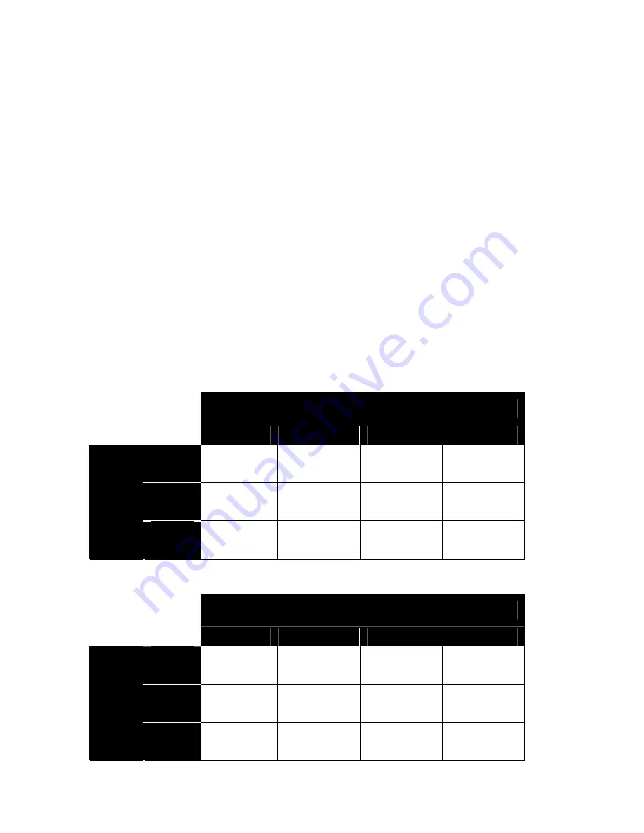
How to use the impedance jumper setting chart:
1) Determine the minimum amplifier impedance (typically either
4- or 8-Ohm). This information can usually be found next to the
speaker outputs located on the receiver or amplifier. If in doubt,
consult the receiver and/or amplifier instruction manual.
2) Next, determine the impedance of a single speaker that will
be used. Use the left-most column.
3) Move to the right of the chart and find the number of speaker
pairs that you plan to connect to the volume control.
4) Finally, move up the column to the very top row. This row will
provide the jumper setting solution. Change the jumper on the
volume control to complete the impedance jumper setting
procedure. Both jumpers must be changed appropriately
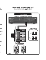
(see diagram in Fig. 1)
Jumper Settings
x1
x2
x4
x8
8
Ohm
1 PAIR 2 PAIRS 4 PAIRS 8 PAIRS
6
Ohm
-
1 PAIR
2 PAIRS 4 PAIRS
Speaker
Impedance
4
Ohm
-
1 PAIR
2 PAIRS 4 PAIRS
CHART A: 8 Ohm Minimum Amplifier
Jumper Settings
x1
x2
x4
x8
8
Ohm
1 PAIR
4 PAIR
8 PAIRS
-
6
Ohm
1 PAIR 2 PAIRS 4 PAIRS 8 PAIRS
Speaker
Impedance
4
Ohm
1 PAIR 2 PAIRS 4 PAIRS 8 PAIRS
CHART B: 4 Ohm Minimum Amplifier


