975-0767-01-01
5
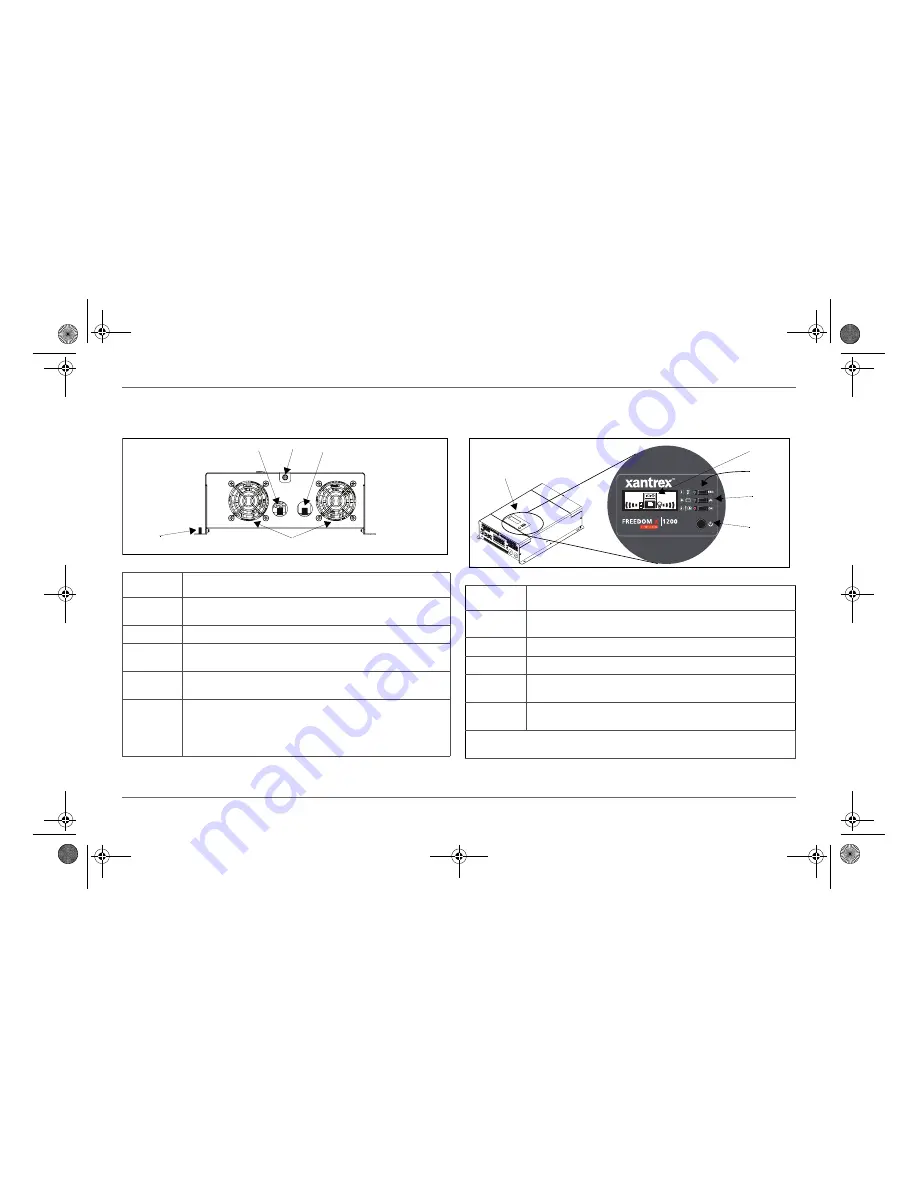
Features
DC Panel
5
4
1
3
2
Feature
Description
1
Positive DC cabling terminal
connects to the positive terminal of the battery
using a battery cable. The terminal nut is pre-installed.
2
Captive nut panel screw
holds the DC compartment cover in place.
3
Negative DC cabling terminal
connects to the negative terminal of the
battery using a battery cable. The terminal nut is pre-installed.
4
Grounding stud
with attached nut provides a ground path for the Freedom X
chassis to the DC system ground.
5
Ventilation grille (openings)
must not be obstructed for the proper operation
of the cooling fan and inverter. When the inverter is mounted, the ventilation
grille must not point up or down.
Cooling fans
turn on when powering loads above 500 watts or when the
internal temperature reaches a set point temperature.
Display Panel
Batt. MODE
AC MODE
VAC
VAC
OUTPUT
INPUT
888
888
5
1
2
4
3
Feature
Description
1
Display panel
displays inverter status and battery status information on the
screen. It is comprised of a display screen, LEDs, select and power buttons.
2
Multi-function LCD screen
shows status information and fault codes.
3
Status LEDs
indicate the mode of operation.
4
Three select buttons
change status information displayed on the screen. Also,
changes inverter settings.
5
Inverter Power button
is pressed for inverter operation. The button stays
down for On and up for Off.
IMPORTANT
: See “Viewing Information on the LCD Screen” on page 37 for detailed
information on the panel’s buttons.
Freedom X Owners Guide.book Page 5 Wednesday, May 11, 2016 10:32 AM
Summary of Contents for 806-1212
Page 2: ...Freedom X Owners Guide book Page ii Wednesday May 11 2016 10 32 AM ...
Page 12: ...Freedom X Owners Guide book Page x Wednesday May 11 2016 10 32 AM ...
Page 14: ...Freedom X Owners Guide book Page ii Wednesday May 11 2016 10 32 AM ...
Page 77: ...Freedom X Owners Guide book Page i Wednesday May 11 2016 10 32 AM ...


