Installation and Configuration
2–4
TM-XR9B-01XN
Front Panel
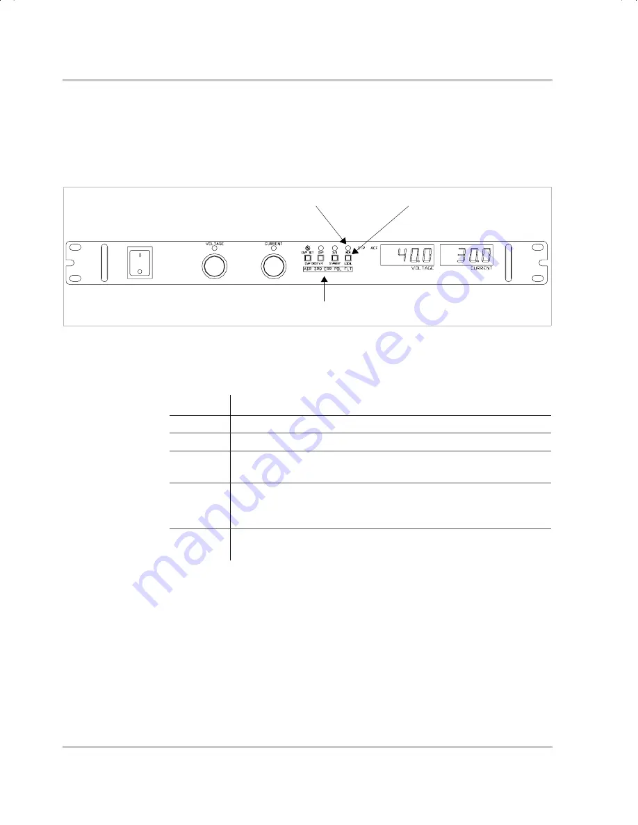
Figure 2-1
shows the front panel of an XFR 1200 Watt supply with
Ethernet/RS-232 Interface
installed. There is a further description of the
Remote Programming LEDs in
Table 2-1
.
Figure 2-1
Power Supply Front Panel with
Ethernet/RS-232 Interface
Installed
(1200 Watt Power Supply Shown)
Table 2-1
Remote Programming LEDs
LED
Description
ADR
Address: Indicates that the master controller is addressing the unit.
SRQ
Service Request: (GPIB only)
ERR
Error: Indicates when a programming error has occurred. You can
clear the ERR LED with an error query command.
FLT
Fault: Indicates that a fault has occurred. The fault bit must be
unmasked. Refer to the status register in
Table 3-8 on page 3–18
.
Momentarily lights if PON SRQ is set to on.
POL
Polarity: Indicates that the polarity user line has been activated.
See
“User Lines Connector” on page 2–26
.
Local Switch (LOCAL)
Remote LED (REM)
Remote Programming LEDs. See table.
TM-XR9B-01XN.book Page 4 Monday, April 19, 2004 9:00 AM
Summary of Contents for ENET-XFR
Page 2: ......
Page 3: ...XFR 1 2kW and 2 8kW Ethernet RS 232 Interface Option Operating Manual...
Page 8: ...vi...
Page 10: ...viii...
Page 14: ...xii...
Page 16: ...xiv...
Page 18: ...xvi...
Page 22: ...1 4...
Page 49: ...User Signals TM XR9B 01XN 2 27 Figure 2 6 User Lines Signal Connector Circuit Block Diagram...
Page 74: ...3 24...
Page 82: ...4 8...
Page 88: ...A 6...
Page 94: ...B 6...
Page 99: ......


