19
2.0 INSTALLATION
©2000 Xantrex Technology Inc.
Wiring
(continued)
Wiring Batteries in Parallel
(continued)
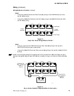
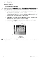
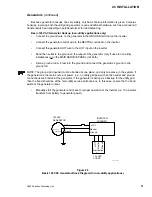
Step 2
Connect the POSITIVE terminal of the first battery string to the POSITIVE terminal of the
second battery string.
Connect the NEGATIVE terminal of the first battery string to the NEGATIVE terminal of the
second battery string.
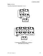
Figure 15
Step 2Two Series Strings Wired in Parallel
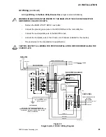
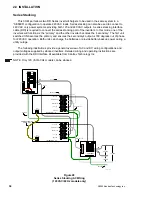
Step 3
Connect a wire from the POSITIVE terminal of the first battery string to the inverters
POSITIVE DC terminal (via a fused device).
Connect the NEGATIVE terminal of the second battery string to the inverters NEGATIVE DC
terminal.
NOTE: Connecting the positive and negative wires to the inverter from different strings ensures a
balanced charge/discharge through the batteries, resulting in longer run times and improved battery
life.
Figure 16
Step 3Series-Parallel Configuration Wired to the Inverter
–
+
–
12 V
12 V
3597-F00-D29
+
–
+
–
12 V
12 V
+
12 V
12 V
–
12 V
12 V
+
–
48 V INVERTER
(Total battery capacity = 100 Ah)
–
+
–
+
–
+
+
Connection from
bank 1 to inverter
positive (+)
terminal
Connection from
bank 2 to inverter
negative ()
terminal
–
+
–
12 V
12 V
3597-F00-D28
+
–
+
–
12 V
12 V
+
–
+
–
12 V
12 V
+
–
+
–
12 V
12 V
+
Series String 1
Series String 2
Parallel
Connection
Parallel
Connection
Summary of Contents for Trace DR Series
Page 1: ...Installation Operator s Manual DR Series Inverter Charger ...
Page 2: ......
Page 81: ......
Page 82: ......
Page 83: ......

