31
2.0 INSTALLATION
©2000 Xantrex Technology Inc.
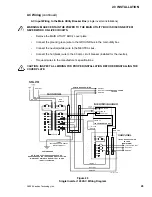
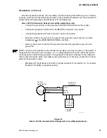
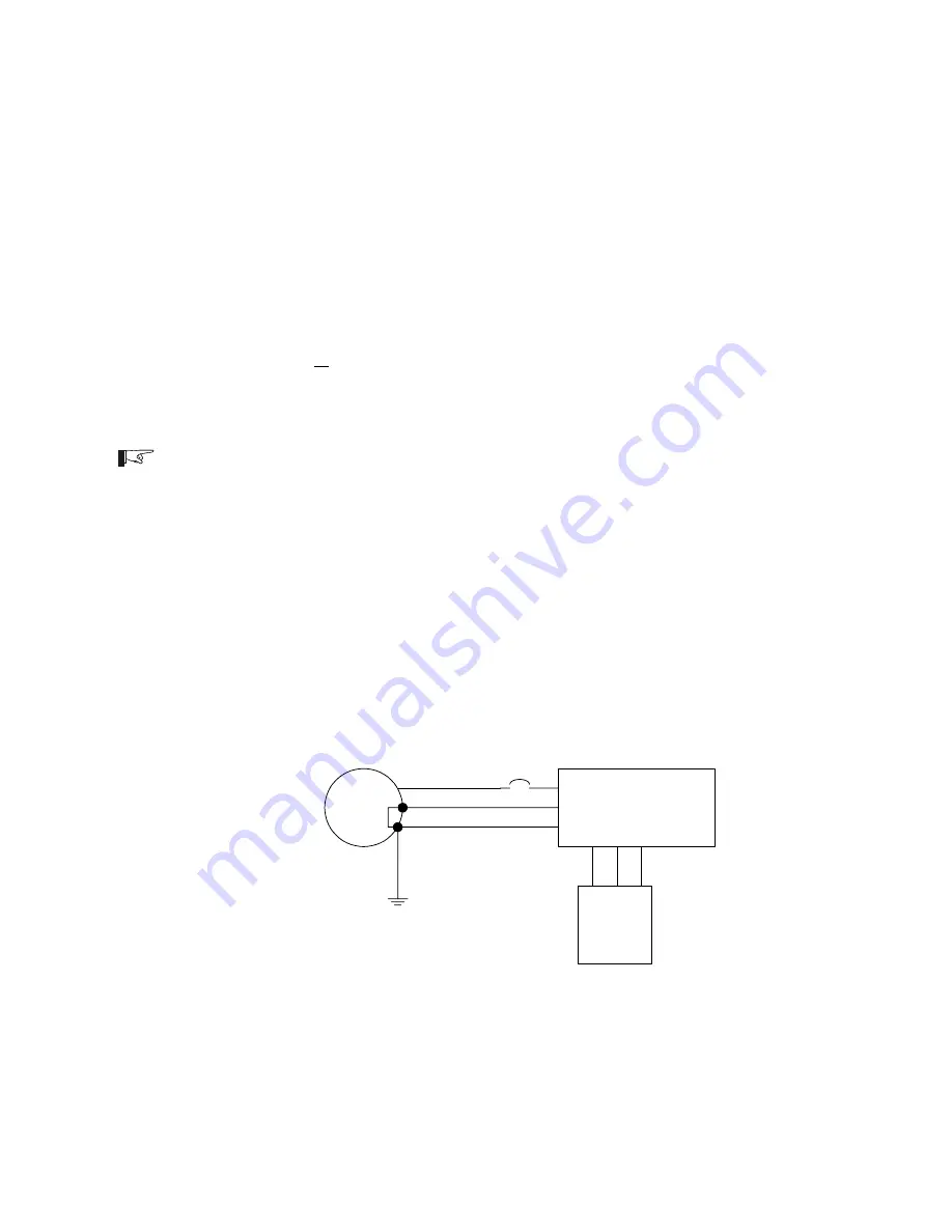
Figure 26
Basic 120 VAC Generator Block Diagram (for non-utility applications)
Generators
(continued)
Because generator hookups can vary widely, only basic hookup information is given. Complex
hookups, involving both the utility and generator, require additional hardware such as a manual AC
transfer switch and possibly an autotransformer for load balancing.
Basic 120 VAC Generator Hookup (non-utility applications only)
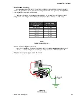
Connect the ground wire on the generator to the GROUND terminal on the inverter.
Connect the generator neutral wire to the NEUTRAL terminal on the inverter.
Connect the generator HOT wire to the HOT input on the inverter.
Bond the neutral to the ground on the output of the generator (only if used in non-utility
installations) or in the MAIN SERVICE PANEL (not both).
Drive a ground rod 68 feet into the ground and connect the generators ground to the
ground rod.
NOTE: The ground and neutral must be bonded at one place, and only one place, in the system. If
the generator is the main source of power, (i.e., no utility grid power) then the neutral and ground
connections are bonded at the generator. If the generator is acting as a backup for the utility grid,
then the bond should be at the main utility service entrance box. In this case, ensure that no bond
exists at the generator output.
Manually start the generator and check for proper operation of the inverter (i.e., the inverter
transfers from battery to generator power).
120 VAC
GENERATOR
HOT
Neutral
Ground
Neutral/
Ground bond
HOT
Neutral
Ground
HO
T
N
eut
ra
l
G
round
INVERTER/
CHARGER
120 VAC
LOADS
3597-A00-016
Distribution
Panel
Summary of Contents for Trace DR Series
Page 1: ...Installation Operator s Manual DR Series Inverter Charger ...
Page 2: ......
Page 81: ......
Page 82: ......
Page 83: ......

