background image


Schnittstelle RS232 

Schnittstellenanschluss RS232 

Der 9-polige Steckverbinder (Typ D) für die serielle Schnittstelle befindet sich auf der 
Geräterückwand. Stiftbelegung: 

Pin Bez.  Beschreibung 

1 - 

Nicht 

belegt 

TXD 

Vom Gerät übertragene Daten 

RXD 

Vom Gerät empfangene Daten 

4 - 

Nicht 

belegt 

5 GND 

Betriebserde 

6 - 

Nicht 

belegt 

RXD2 

Empfangene sekundäre Daten (nur adressierbarer RS232 

Betrieb) 

TXD2 

Übertragene sekundäre Daten (nur adressierbarer RS232 

Betrieb)  

GND 

Betriebserde (nur adressierbarer RS232 Betrieb) 

RS232-Anschlüsse für Einzelgerät 

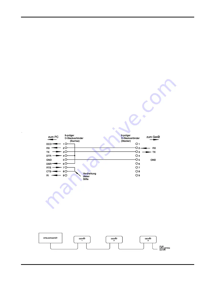
Zur Fernbedienung von nur einem Gerät müssen lediglich die Stifte 2, 3 und 5 an den Computer 
angeschlossen werden. Um jedoch einen einwandfreien Betrieb zu gewährleisten, müssen am 
PC-seitigen Steckverbinder  die Stifte 1, 4 und 6 sowie 7 und 8 gebrückt werden - siehe hierzu 
nachfolgendes Diagramm. Die Gerätestifte 7 und 8 dürfen 

nicht

 an den PC angeschlossen 

werden; d.h. auf keinen Fall ein voll verdrahtetes 9-poliges Kabel verwenden! 

Die Baudrate wird entsprechend den im Abschnitt „Wahl der Adresse und Baudrate“ gemachten 
Angaben eingestellt, die übrigen Parameter sind wie folgt festgelegt: 

Startbits:    1 

Parität:  Keine 

Datenbits:  8 

Stopbits:  1 

 Adressierbare RS232-Anschlüsse 

Für den adressierbaren RS232-Betrieb werden zusätzlich die Stifte 7, 8 und 9 der 
Gerätesteckverbindung benutzt. Mit einer einfachen Kabelgarnitur kann eine Verkettung 
zwischen maximal 32 Geräten erfolgen, wie nachstehend gezeigt. 


 84 

Summary of Contents for XDL 35-5

Page 1: ...XDL Series Digital Programmable Single Output DC Power Supply Operating Manual XDL 35 5 XDL 35 5P XDL 56 4 XDL 56 4P...

Page 2: ...re the property of their respective owners and are used herein for identification purposes only Notice of Copyright Xantrex International All rights reserved Disclaimer UNLESS SPECIFICALLY AGREED TO I...

Page 3: ...35 Instructions en Francais S curit 36 Installation 37 Connexions 39 Utilisation initiale 41 Fonctionnement manuel 44 Fonctionnement distance XDL 35 5P XDL 56 4P seulement 52 Commandes distance 62 Mai...

Page 4: ...amento remoto solo per il XDL 35 5P XDL 56 4P 114 Comandi remoti 124 Manutenzione 128 Instrucciones en Espa ol Seguridad 129 Instalaci n 130 Conexiones 131 Funcionamiento inicial 133 Funcionamiento ma...

Page 5: ...ovides enhanced current setting and measurement resolution of 0 1mA The product of voltage and current can be displayed at any time by pressing the VxA button The power is displayed to a resolution of...

Page 6: ...bs multiple devices can be connected A Windows device driver is supplied which creates a virtual COM port enabling USB to be used with applications that do not directly support it XDL series supplies...

Page 7: ...set level for a change in load current from full load to half load or vice versa Voltage Programming Speed Maximum time required for output to settle within 1 of its total excursion for resistive loa...

Page 8: ...ut voltage and current settings in a quasi analogue mode INTERFACES XDL 35 5P XDL 56 4P only Full remote control facilities are available through the optional RS232 GPIB and USB interfaces Setting and...

Page 9: ...ormance A According to EN61326 the definitions of performance criteria are Performance criterion A During test normal performance within the specification limits Performance criterion B During test te...

Page 10: ...hibited The protective action must not be negated by the use of an extension cord without a protective conductor When the instrument is connected to its supply terminals may be live and opening the co...

Page 11: ...are used for replacement The use of makeshift fuses and the short circuiting of fuseholders are prohibited Mains Lead When a three core mains lead with bare ends is provided it should be connected as...

Page 12: ...a remote control interface When the rear panel terminals are used remote sense should always be selected to ensure that output regulation is maintained within specification RS232 XDL 35 5P XDL 56 4P o...

Page 13: ...larm Outputs The recessed 2 pin connector marked Alarm provides access to an opto isolated NPN switching transistor the function of which can be set from the keyboard see the Alarms section of this ma...

Page 14: ...essages prompt guide or warn the user such that entry or control errors are minimised Where some of these features e g beeps or flashing indicators are considered unnecessary by regular users the opti...

Page 15: ...necessary to either turn the output off so that the display permanently shows the current limit or to press VIEW V I LIMITS which causes the current limit to be displayed until 3 seconds after movemen...

Page 16: ...urn to its original reading before SET V was pressed Entering a voltage outside the range maximum including trying to enter 3 digits before the decimal point or trying to enter more than 5 digits will...

Page 17: ...ored The current limit can also be set using the rotary jog control Pressing JOG SET I will illuminate the key and the JOG indicator under the digit that was last jogged will flash Whilst the I key is...

Page 18: ...onnection to the Load The load should be connected to the positive red and negative black OUTPUT terminals Both are fully floating and either can be connected to ground Remote Sensing The instrument h...

Page 19: ...imit settings Note that the output terminals are rated at 15A maximum if several outputs are operated in parallel to source higher currents than this the junction should be made at a separate point no...

Page 20: ...Amps although transients can be much higher Output Power V x A If SHIFT V x A is pressed the voltage display shows the product of measured output voltage x measured current and the current display sho...

Page 21: ...the settings flash to indicate preview mode Any number of stores can be previewed by pressing one number after another i e without having to press SHIFT RECALL each time before the selection is confi...

Page 22: ...56 4 Voltage 1 000V Current Limit 1 000A OVP 40V XDL 35 5 62V XDL 56 4 OCP 5 5A XDL 35 5 4 4A XDL 56 4 Output Output off local Sense Settings 00 Output always off at power up 26 Alarm output closed w...

Page 23: ...ud rate Press SHIFT Bus Type to display the currently selected bus type To change to another bus type scroll through the available types using the rotary control until the required type is displayed P...

Page 24: ...PC end between pins 1 4 and 6 and between pins 7 and 8 see diagram Pins 7 and 8 of the instrument must not be connected to the PC i e do not use a fully wired 9 way cable Baud Rate is set as describe...

Page 25: ...t is not addressable and will not respond to any address commands This allows the instrument to function as a normal RS232 controllable device This mode may be locked by sending the Lock Non Addressab...

Page 26: ...nstrument 03H Universal Unaddress control code 04H Lock Non Addressable mode control code 18H Universal Device Clear Talk mode will also be cancelled when the instrument has completed sending a respon...

Page 27: ...he establishment of a virtual COM port is done automatically each time the instrument is connected to the PC via USB in the future Further virtual COM ports are created for each additional instrument...

Page 28: ...esponse formatter to be reset thus clearing the output queue The parser will then start parsing the next PROGRAM MESSAGE UNIT from the input queue See the Status Reporting section for further informat...

Page 29: ...up data has been requested but the store specified contains corrupted data This indicates either a hardware fault or a temporary data corruption which can be corrected by writing data to the store aga...

Page 30: ...the bus The Status Byte Register is read either by the STB command which will return MSS in bit 6 or by a Serial Poll which will return RQS in bit 6 The Service Request Enable register is set by the...

Page 31: ...Query Error Register 0 Parallel Poll Enable Register 0 Registers marked thus are specific to the GPIB section of the instrument and are of limited use in an RS232 environment The instrument will be i...

Page 32: ...ose which are specified as addressable RS232 control codes WHITE SPACE is ignored except in command identifiers e g C LS is not equivalent to CLS The high bit of all characters is ignored The commands...

Page 33: ...ommand nr1 A number with no fractional part i e an integer nr2 A number in fixed point format e g 11 52 0 78 etc The commands which begin with a are those specified by IEEE Std 488 2 as Common command...

Page 34: ...t voltage by step size INCV1V increment the output voltage by step size with verify DECV1 decrement the output voltage by step size DECV1V decrement output voltage by step size with verify INCI1 incre...

Page 35: ...uential nature of all operations PRE nrf Set the Parallel Poll Enable Register to the value nrf PRE Returns the value in the Parallel Poll Enable Register in nr1 numeric format The syntax of the respo...

Page 36: ...ration values Having entered calibration mode follow the table below To increment to the next step press OK The calibration must be done in sequence At the end of calibration press OK to store the cal...

Page 37: ...M o p V span 8 56V 2A 2V 0 001A 1mA 0 5mA milli ammeter o p A offset 9 56V 2A 2V 0 001A 0 001 on display milli ammeter A readback zero 10 56V 500mA 2V 0 1mA 0 1mA 0 05mA milli ammeter o p mA offset 11...

Page 38: ...anchement la terre La s curit de l instrument ne doit pas tre annul e par l utilisation de rallonge sans conducteur de protection Lorsque l instrument est reli au secteur il est possible que les borne...

Page 39: ...eure du connecteur d entr e IEC Pour changer de fusible retirer le cordon et ouvrir le tiroir porte fusible l aide d un outil adapt Le type correct de fusible secteur est 20 x 5mm 250V HBC retardement...

Page 40: ...ique s rie XDL La baie acceptera 1 2 ou 3 unit s simples ou une unit triple et une simple une pi ce d obturation est galement disponible pour les positions non utilis es de la baie Ventilation L alime...

Page 41: ...une interface de t l commande Si l on utilise les bornes du panneau arri re la d tection distance devra toujours tre s lectionn e pour assurer que la r gulation de sortie sera maintenue dans les sp c...

Page 42: ...me Le connecteur 2 broches en retrait marqu Alarm alarme donne acc s un transistor de basculement NPN opto isol dont la fonction peut tre r gl e partir du clavier voir la section Alarmes de ce manuel...

Page 43: ...ant la facilit d utilisation Ceci a t r alis en demandant l utilisateur de confirmer OK les nouveaux r glages num riques avec l option ESCAPE pour s chapper tout moment ou m me simplement marquer une...

Page 44: ...ite de celui que l on r gle pas pas restent inchang s jusqu ce que le r glage pas pas franchisse le maximum ou le minimum de la plage auquel cas ils sont r gl s z ro Par exemple 33 65V passe 34 65V pu...

Page 45: ...n e 35V 3A 15V 5A ou 35V 500mA XDL 35 5 56V 2A 25V 4A 56V 500mA XDL 56 4 les indicateurs s allument sous la plage inscrite imm diatement au dessus d eux et dans le cas de la plage 500mA l indicateur e...

Page 46: ...ogrammera 0 000V Appuyer n importe quel moment sur ESCAPE au cours de la s quence ou ne plus appuyer sur aucune touche pendant les 10 secondes qui suivent l action pr c dente renverront l affichage sa...

Page 47: ...n importe quel moment sur ESCAPE au cours de la s quence ou ne plus appuyer sur aucune touche pendant les 10 secondes qui suivent l action pr c dente renverront l affichage sa lecture d origine avant...

Page 48: ...RANGE ou RANGE avec la sortie active fera clignoter la touche ON OFF marche arr t de la sortie ainsi que la touche OK La sortie peut tre coup e avec la touche ON OFF et la plage peut alors tre chang e...

Page 49: ...ateurs pour produire des tensions CC allant jusqu 300V CC La tension maximale admissible entre n importe quelle borne et la terre est de 300V CC AVERTISSEMENT De telles tensions sont excessivement dan...

Page 50: ...uyer sur OK pour confirmer le nouveau r glage pour quitter sans saisir une nouvelle valeur appuyer sur ESCAPE Le r glage par d faut d usine est de 5 50A Si l OCP se d clenche l affichage pr sente le m...

Page 51: ...tion distance ne sont pas enregistr s Pour enregistrer une configuration appuyer sur SHIFT STORE n d enregistrement OK le n d enregstrement est une touche de 0 9 Apr s avoir appuy sur les touches SHIF...

Page 52: ...nne un bip de confirmation lorsque la saisie du num ro 2 chiffres est termin e Code Fonction 00 Sortie toujours coup e la mise sous tension r glage par d faut d usine 01 Statut de la sortie la mise so...

Page 53: ...6 4P seulement Adresse 11 XDL 35 5P XDL 56 4P seulement Messages d erreur Les erreurs mat rielles suivantes sont indiqu es par l apparition du num ro d erreur appropri l cran La touche OK va clignoter...

Page 54: ...e pour afficher le type de bus actuellement s lectionn Pour passer un autre type de bus faire d filer les types disponibles en utilisant la molette rotative jusqu ce que le type voulu s affiche Appuye...

Page 55: ...au PC Toutefois pour assurer un fonctionnement correct il faut r aliser des liaisons dans le connecteur l extr mit PC entre les broches 1 4 et 6 et entre les broches 7 et 8 voir le sch ma Il ne faut...

Page 56: ...essable RS232 Dans ce manuel par 20H etc on entend 20 en hexad cimal Codes de contr le d interface adressable RS232 Tous les instruments devant tre utilis s sur le bus adressable RS232 utilisent le je...

Page 57: ...sal Device Clear initialisation dispositif universel Avant qu une r ponse puisse tre lue sur un instrument il doit tre en mode d mission suite la transmission du code de contr le Talk Address 14H suiv...

Page 58: ...nvenable A condition que les invites standard de Windows soient correctement suivies Windows installera le pilote appropri et tablira un port COM virtuel dans le PC Le num ro du nouveau port COM d pen...

Page 59: ...sage de programme a t lu par l analyseur syntaxique ou que la file d attente d entr e contient plus d un message END fin ceci indique que l instrument a t INTERRUPTED interrompu qu une erreur est g n...

Page 60: ...d tat complet de l instrument Noter que certains registres sont sp cifiques la section GPIB de l instrument et que leur utilisation est donc restreinte dans un environnement RS232 Standard Event Stat...

Page 61: ...ed error Erreur non termin e Bit 1 Non utilis Bit 0 Op ration termin e R gl en r ponse la commande OPC Limit Event Status Register registre d tat d v nement limite et Limit Event Status Enable Registe...

Page 62: ...me IEEE 488 2 contient la fois le message Requesting Service et le message Master Status Summary r sum d tat principal RQS est renvoy en r ponse Serial Poll et MSS en r ponse la commande STB Bit 5 ESB...

Page 63: ...0 Les registres marqu s de cette mani re sont sp cifiques la section GPIB de l instrument et leur utilisation est restreinte dans un environnement RS232 L instrument sera l tat local le clavier actif...

Page 64: ...fi e dans la liste de commandes Chaque r ponse se termine par le code 0DH retour chariot CR suivi du code 0AH saut de ligne LF WHITE SPACE espace blanc est d fini sous forme de code de caract re 00H 2...

Page 65: ...commande est enti rement ex cut e avant le d marrage de la commande suivante Toutes les commandes sont s quentielles et le message de fin d ex cution est g n r imm diatement apr s ex cution dans tous...

Page 66: ...1 nr2 rmt o nr2 est en Volts DELTAI1 renvoie la taille de pas d intensit de sortie la r ponse est DELTAI1 nr2 rmt o nr2 est en Volts INCV1 incr mente la tension de sortie de la taille du pas INCV1V in...

Page 67: ...p rations PRE nrf R glage du Parallel Poll Enable Register la valeur nrf PRE Renvoi de la valeur dans le Parallel Poll Enable Register sous format num rique nr1 Syntaxe de la r ponse nr1 rmt SRE nrf R...

Page 68: ...r un personnel exp riment utilisant le manuel d entretien que l on peut se procurer directement aupr s du constructeur ou de ses agents l tranger Nettoyage S il faut nettoyer l instrument utiliser un...

Page 69: ...e Schutzwirkung darf durch Verwendung eines Verl ngerungskabels ohne Schutzleiter nicht aufgehoben werden Ist das Ger t an die elektrische Versorgung angeschlossen so k nnen die Klemmen unter Spannung...

Page 70: ...kers Zum Wechseln der Sicherung das Netzkabel abziehen und das Sicherungsfach mit einem geeigneten Werkzeug ffnen Die Sicherung ist vom Typ 20 x 5 mm 250 V Hochleistungssicherung HBC tr ge mit folgend...

Page 71: ...chubgeh use kann bis zu drei Ger te mit einer 1 HE oder ein Dreifachger t und ein Einzelger t aufnehmen F r nicht verwendete Einschubpl tze sind au erdem Abdeckblenden erh ltlich Bel ftung Das Netzger...

Page 72: ...Tastatur oder eine Fernsteuerungs Schnittstelle gew hlt Bei Verwendung der r ckseitigen Anschl sse sollte immer auch die Zuleitungskompensation gew hlt werden damit die Stabilisierung der Ausgangsspa...

Page 73: ...e Der versenkt eingebaute 2 polige Anschluss mit der Bezeichnung Alarm ist mit einem opto gekoppelten NPN Schalttransistor verbunden dessen Funktion von der Tastatur aus eingestellt werden kann siehe...

Page 74: ...kg ngig gemacht werden Andererseits kann der Anwender auch einfach warten bis das Ger t nach einer gewissen Zeitspanne automatisch auf die urspr ngliche Einstellung zur ckkehrt Zus tzlich wird der Anw...

Page 75: ...eich bei einer Schrittgr e von 1 V wechselt 33 65 V auf 34 65 V und schlie lich auf 35 00 V Bei einer Schrittgr e von 0 1 A wechselt 0 160 A auf 0 060 A und schlie lich auf 0 001 A Folgende Schrittgr...

Page 76: ...mA XDL 35 5 56 V 2 A 25 V 4 A 56 V 500 mA XDL 56 4P Diese Anzeigen leuchten direkt unter dem Bereich auf der ganz oben auf dem Ger t aufgedruckt ist Im Falle des Bereichs 500 mA wird der Hinweis mA an...

Page 77: ...r durch das Unterlassen weiterer Eingaben in den n chsten 10 Sekunden kehrt das Display auf den Wert zur ck der vor Dr cken der Taste SET V G ltigkeit hatte Wird eine Spannung au erhalb des Maximalber...

Page 78: ...hs eingegeben gilt auch bei der Eingabe von 2 Ziffern vor dem Dezimalkomma oder wenn versucht wird mehr als 4 Ziffern einzugeben ert nt ein zweifaches Warnsignal die zuletzt gedr ckte Taste wird ignor...

Page 79: ...s eingestellte Strom oder Spannungsgrenzwert durch einen neu gew hlten Bereich berschritten so ist die Bereichswahl zwar g ltig doch wird die Einstellung auf den Maximalwert des neu gew hlten Bereichs...

Page 80: ...esch tzt werden Auf keinen Fall d rfen die Ausgangsklemmen in einem solchen Fall ber hrt werden S mtliche Anschl sse an den Klemmen d rfen erst dann erfolgen wenn alle betreffenden Netzger te ausgesch...

Page 81: ...Durch Dr cken auf OK wird die neue Einstellung best tigt Mit der Taste ESCAPE kann die Einstellung r ckg ngig gemacht werden Der werksseitig voreingestellte Wert ist 5 50 A Wurde der berstromschutz au...

Page 82: ...den gespeicherten Parametern handelt es sich um Bereich Spannung Strombegrenzungs wert OVP und OCP Der Ausgangsstatus und die Einstellungen f r den Fernf hler werden nicht gespeichert Um eine Einstel...

Page 83: ...aste Zusatzfunktionen vom Benutzer ver ndert werden Alle Funktions nderungen siehe folgende Tabelle wird durch Dr cken der Tastenfolge SHIFT nn eingeleitet wobei sich nn auf die 2 stellige Nummer in d...

Page 84: ...P XDL 56 4P Adresse 11 nur XDL 35 5P XDL 56 4P Fehlermeldungen Die folgenden Hardware Fehler werden mit der entsprechenden Nummer im Display angezeigt Die Taste OK blinkt Wird sie gedr ckt so wird der...

Page 85: ...tellt sein Die Tasten SHIFT und Bus Type dr cken um den aktuellen Steuerbus anzuzeigen Soll auf einen anderen Bus gewechselt werden mit dem Drehknopf die einzelnen Optionen durchgehen bis der gew nsch...

Page 86: ...den Computer angeschlossen werden Um jedoch einen einwandfreien Betrieb zu gew hrleisten m ssen am PC seitigen Steckverbinder die Stifte 1 4 und 6 sowie 7 und 8 gebr ckt werden siehe hierzu nachfolge...

Page 87: ...zeichen sind f r die adressierbare RS232 Schnittstellensteuerung reserviert In dieser Anleitung bedeutet 20H usw 20 in hexadezimaler Schreibweise Steuercodes der adressierbaren RS232 Schnittstelle Bei...

Page 88: ...lgt von einer ger tefremden Adresse 14H Talk Address f r jedes beliebige Ger t 03H Universal Unaddress Steuercode 04H Lock Non Addressable Modus Steuercode 18H Universal Device Clear Bevor die Antwort...

Page 89: ...n Treibers erfolgt indem das Ger t ber ein normales USB Kabel an einen PC angeschlossen wird Durch die Plug and Play Funktionalit t unter Windows wird die am USB Port angeschlossene neue Hardware norm...

Page 90: ...d ein UNTERMINATED Fehler generiert Dies bewirkt dass ein Query Error Bit im Standard Event Status Register gesetzt der Wert von 3 ins Query Error Register geschrieben und der Parser zur ckgestellt wi...

Page 91: ...PPC mit anschlie endem 69H PPE Die Antwort auf die Parallelabfrage vom Ger t lautet dann 00H wenn RQS gleich 0 ist und 01H wenn RQS gleich 1 ist W hrend der Parallelabfrageantwort sind die DIO Schnitt...

Page 92: ...fehler auftritt Die entsprechende Fehlernummer wird im Query Error Register wie folgt aufgezeichnet 1 Interrupted Error Unterbrechungsfehler 2 Deadlock Error Blockierungsfehler 3 Unterminated Error Ni...

Page 93: ...efiniert ist enth lt sowohl die Requesting Service Meldung Serviceanforderung als auch die Master Status Summary Meldung Als Antwort auf ein Serial Poll Serienabfrage wird RQS und als Antwort auf den...

Page 94: ...m Zeichen versehenen Register beziehen sich spezifisch auf den GPIB Teil des Ger tes und sind daher in einer RS232 Umgebung nur begrenzt brauchbar Das Ger t befindet sich im lokalen Betriebsmodus mit...

Page 95: ...hlie lich definiert ausgenommen sind diejenigen die als addressable RS232 Steuercodes festgelegt sind WHITE SPACE bleibt unber cksichtigt ausgenommen bei Befehlskennzeichnern wie z B C LS entspricht n...

Page 96: ...r 12 Jede Zahl wird nach ihrem Empfang je nach erforderlicher Genauigkeit konvertiert die ihrer Verwendung entspricht und dann gerundet um den Wert des Befehls zu erhalten nr1 Eine Nummer ohne Brucht...

Page 97: ...DELTAI1 nr2 rmt mit nr2 in Ampere INCV1 Ausgangsspannung um die Schrittgr e erh hen INCV1V Ausgangsspannung um die Schrittgr e erh hen mit Verifizierung DECV1 Ausgangsspannung um die Schrittgr e senk...

Page 98: ...e geschieht dies unmittelbar nach Ausf hrung des Befehls OPC Query Operation Complete Status Abfrage des Status Vorgang abgeschlossen Die Syntax der Antwort lautet 1 rmt Aufgrund des sequentiellen Abl...

Page 99: ...paraturdienst f r Ger te bereit bei denen St rungen auftreten Falls die Besitzer ihre eigene Wartungsarbeiten durchf hren wollen sollten diese nur von gelernten Fachkr ften und in Verbindung mit der W...

Page 100: ...tezione non deve essere negata attraverso l uso di un cavo di prolunga privo del filo di collegamento a terra Quando lo strumento alimentato alcuni morsetti sono sotto tensione e l apertura dei coperc...

Page 101: ...e d ingresso a norma IEC Per sostituire il fusibile staccare il cavo di alimentazione ed aprire il cassetto portafusibili con un utensile idoneo Utilizzare un fusibile ad alto punto di fusione da 20 x...

Page 102: ...o di ospitare 1 2 o 3 alimentatori singoli od un alimentatore triplo e uno singolo anche possibile acquistare supporti di chiusura per le posizioni del rack non utilizzate Ventilazione Il raffreddamen...

Page 103: ...ramite la tastiera o l interfaccia di controllo remota Quando si utilizzano i morsetti sul pannello posteriore occorre selezionare sempre la modalit remote sense per mantenere sempre i valori previsti...

Page 104: ...re a 2 pin incassato contrassegnato dalla dicitura Alarm Allarme consente di accedere al transistor di commutazione NPN optoisolato la cui funzione pu essere impostata dalla tastiera vedi la sezione A...

Page 105: ...nalatori LED e la comparsa di messaggi sullo schermo sono destinate a minimizzare la possibilit di errori di digitazione o di controllo Gli utenti abituali che ritengono superflua l attivazione di alc...

Page 106: ...e variazione graduale non pu essere annullata tramite i tasti numerici o le funzioni di SHIFT ma pu essere disattivata mentre la funzione SHIFT attiva Nella modalit tensione costante la parte destra d...

Page 107: ...ando si preme il tasto VIEW V I LIMITS per segnalare il limite impostato per la tensione la corrente REM che si accende quando lo strumento viene gestito da un interfaccia remota solo per il XDL 35 5P...

Page 108: ...perazione o la mancata pressione di un tasto entro 10 secondi dalla pressione dell ultimo tasto ripristina il valore visualizzato prima della pressione del tasto SET V La digitazione di un valore di t...

Page 109: ...no e fa s che venga ignorato l ultimo tasto premuto Il limiti di corrente pu essere impostato anche tramite la manopola di variazione graduale Premendo JOG SET V si illumina il tasto V e lampeggia il...

Page 110: ...e valida sulla gamma 15 V compito dell utente cambiarlo Collegamento agli utilizzatori Collegare gli utilizzatori ai morsetti contrassegnati OUTPUT positivo rosso e negativo nero Entrambi sono morsett...

Page 111: ...fine di erogare correnti elevate Qualora si colleghino pi strumenti in parallelo la tensione erogata corrisponder a quella dello strumento che eroga la tensione pi alta fino a quando la corrente prel...

Page 112: ...sione e corrente predefiniti Una volta individuata ed eliminata la causa dell intervento dell OVP oppure una volta cambiato il valore max per l OVP possibile reinserire l erogazione di corrente Si not...

Page 113: ...ri relativi allo stato dell uscita e al rilevatore remoto Per memorizzare i valori premere SHIFT STORE memoria il n della memoria OK il numero della memoria uno dei tasti da 0 a 9 Una volta premuti di...

Page 114: ...sotto la spia SHIFT si spegne e viene inserito il cicalino per confermare la digitazione del numero a 2 cifre Codice Funzione 00 Erogazione sempre disinserita all accensione predefinita in fabbrica 0...

Page 115: ...DL 56 4P Indirizzo 11 solo per il XDL 35 5P XDL 56 4P Messaggi di errore I seguenti errori hardware vengono segnalati dalla comparsa del rispettivo numero di errore sul display Il tasto OK lampeggia e...

Page 116: ...almente selezionato Per cambiarlo visualizzare tutti i tipi disponibili ruotando la manopola sullo strumento fino a quando compare il tipo desiderato Premere OK per selezionare il tipo visualizzato o...

Page 117: ...e anche previsto il collegamento al PC tra i pin 1 4 e 6 e i pin 7 e 8 come illustra lo schema qui sotto I pin 7 e 8 non devono essere collegati al PC ovvero non richiesto l impiego di un connettore c...

Page 118: ...l interfaccia nei comandi dello strumento la sola eccezione riportata qui di seguito ed interessa i codici CR ed LF e i codici XON ed XOFF All accensione lo strumento entra automaticamente nella modal...

Page 119: ...corrispondono all indirizzo univoco dello strumento interessato come per il codice di controllo Listen address di cui sopra Una volta invitato al dialogo lo strumento invia l eventuale messaggio di ri...

Page 120: ...river e a creare una porta COM virtuale nel PC Il numero della porta COM dipende dal numero di porte COM gi presenti sul PC La porta COM virtuale pu essere gestita dagli applicativi Windows esattament...

Page 121: ...INATOR codice finale messaggio programma o la coda dei messaggi in entrata contiene pi di un messaggio END fine lo strumento riceve il codice INTERRUPTED e viene generato un errore Questo comporta l i...

Page 122: ...registri sono specifici alla sezione GPIB dello strumento e non hanno molta pertinenza con l ambito RS232 Standard Event Status Register e Standard Event Status Enable Register registro stati eventi o...

Page 123: ...imiti di corrente o di tensione nonch lo storico delle condizioni che hanno provocato l intervento delle protezioni dall ultima lettura I bit eventualmente impostati nel Limit Event Status Register ch...

Page 124: ...s Register corrisponde a un bit impostato nello Standard Event Status Enable Register Bit 4 MAV il Message Available Bit Bit messaggio disponibile Si imposta quando lo strumento ha un messaggio di ris...

Page 125: ...Register 0 I registri seguiti da questo simbolo interessano solo la sezione GPIB dello strumento ed hanno poca pertinenza nell ambito RS232 Lo strumento funziona nella modalit locale con la tastiera...

Page 126: ...re da 00H a 20H incluso ad eccezione di quelli specificati come codici di controllo addressable RS232 RS232 indirizzabile WHITE SPACE viene ignorato ad eccezione di quando si trova negli identificator...

Page 127: ...po l esecuzione Si utilizza la seguente nomenclatura rmt RESPONSE MESSAGE TERMINATOR nrf Il numero 12 pu essere espresso come 12 12 00 1 2 e1 e 120 e 1 I numeri una volta ricevuti vengono trasformati...

Page 128: ...erogata su nrf Volt DELTAI1 nrf imposta il passo corrente erogata su nrf Ampere DELTAV1 ritorna il valore del passo della tensione erogata la risposta DELTAV1 nr2 rmt dove nr2 viene espresso in Volt D...

Page 129: ...valore nello Standard Event Status Register al formato numerico nr1 Il registro viene successivamente svuotato La sintassi della risposta nr1 rmt IST Ritorna il messaggio locale ist definito dallo St...

Page 130: ...o I numeri dei messaggi di errore non vengono visualizzati sul display ma vengono memorizzati nell Execution Error Register dove possibile leggerli attraverso le interfacce di controllo remote vedi la...

Page 131: ...errupci n intencional La acci n protectora no debe negarse por el uso de una extensi n de cable sin conductor protector Cuando el instrumento est conectado a su suministro es posible que queden sin pr...

Page 132: ...nferior del conector de entrada IEC Para cambiar el fusible quite el cable y abra el compartimento de fusibles con una herramienta adecuada El tipo correcto de fusible de corriente es de 20 x 5 mm 250...

Page 133: ...ativo El funcionamiento de la detecci n remota se selecciona desde el teclado o a trav s de la interfaz de control remoto s lo XDL 35 5P XDL 56 4P La luz REMOTE SENSE se enciende cuando se selecciona...

Page 134: ...1 DC1 DT1 C0 E2 La direcci n GPIB se ajusta desde el teclado USB s lo XDL 35 5P XDL 56 4P El puerto USB se conecta a la toma de tierra del instrumento y acepta un cable est ndar USB Las funciones plug...

Page 135: ...sivos en un sistema final y que el uso sea sencillo Esto se ha conseguido solicitando al usuario que confirme OK los nuevos ajustes num ricos con la opci n de utilizar ESCAPE en cualquier punto o incl...

Page 136: ...Los d gitos a la derecha del que se cambia siguen igual a menos que el paso de cambio supere o no llegue al m ximo m nimo de voltaje en cuyo caso se ajustan a cero Por ejemplo 33 65V se ajusta en 34 6...

Page 137: ...to seleccionado 35V 3A 15V 5A o 35V 500mA XDL 35 5 56V 2A 25V 4A 56V 500mA XDL 56 4 Los indicadores se encienden bajo el r gimen impreso inmediatamente por encima de ellos y en el caso del r gimen 500...

Page 138: ...despu s de 10 segundos de pulsar la anterior la pantalla regresar a su lectura original antes de pulsarse SET V Si se introduce un voltaje fuera del r gimen m ximo incluso intentar introducir 3 d git...

Page 139: ...ulsar la anterior la pantalla regresar a su lectura original antes de pulsarse SET I Si se introduce un voltaje fuera del r gimen m ximo incluso intentar introducir 2 d gitos antes de la coma decimal...

Page 140: ...puede desconectar con la tecla ON OFF y el r gimen se puede cambiar pulsando OK o bien se puede pulsar OK directamente en cuyo caso la salida se desconecta autom ticamente y se puede cambiar el r gim...

Page 141: ...lida para este uso Bajo ninguna circunstancia se deben tocar los terminales de salida cuando se conecta la unidad para dicho uso Todas las conexiones en los terminales se deben hacer con la alimentaci...

Page 142: ...juste predeterminado de f brica es 5 50A Si se deconecta la OCP la pantalla mostrar el mensaje OCP triP y la salida se desconectar Si se pulsa ESCAPE en este punto se borrar el mensaje y la pantalla m...

Page 143: ...OCP El estado de salida y el ajuste de detecci n remota no se almacenan Para almacenar una configuraci n pulse SHIFT STORE n mero de memoria OK el n mero de memoria es cualquier tecla entre 0 y 9 Desp...

Page 144: ...alida siempre est desconectada en el encendido ajuste predeterminado de f brica 01 El estado de la salida en el encendido es el mismo que cuando se apag el instrumento por ltima vez 20 Salida de alarm...

Page 145: ...S232 9 600 baudios s lo XDL 35 5P XDL 56 4P Direcci n 11 s lo XDL 35 5P XDL 56 4P Mensajes de error Los siguientes errores de hardware se indican con el n mero de error correspondiente en la pantalla...

Page 146: ...Pulse SHIFT Bus Type para mostrar el tipo de bus seleccionado Para cambiar a otro tipo de bus despl cese por los tipos disponibles por medio del control giratorio hasta que se muestre el tipo necesari...

Page 147: ...est n conectadas al PC Sin embargo para el funcionamiento correcto se deben realizar enlaces en el conector del PC entre las clavijas 1 4 y 6 y entre las clavijas 7 y 8 ver diagrama Las clavijas 7 y 8...

Page 148: ...de Control de la Interfaz RS232 Direccionable Todos los instrumentos pensados para ser utilizados en la interfaz RS232 direccionable utilizan el siguiente conjunto de c digos de control de la interfa...

Page 149: ...r a hablar mandando el c digo de control Talk Address 14H seguido de un car cter nico que tiene los 5 bits de m s abajo correspondientes a la direcci n nica del instrumento que se requiere como el c d...

Page 150: ...ws el sistema operativo instalar el controlador correspondiente y establecer un puerto COM virtual en el PC El n mero del nuevo puerto COM depender del n mero de puertos COM que ya existan en el PC El...

Page 151: ...bit del Query Error se configure en Standard Event Status Register que se coloque un valor de 1 en el Query Error Register y que el formateador de respuestas se reinicialice limpiando de este modo la...

Page 152: ...ctivaci n de estado de eventos est ndar Standard Event Status Enable Register Estos dos registros est n implementados tal y como requiere la norma IEEE Std 488 2 Todos los bits configurados en el Stan...

Page 153: ...vent Status Register y registro de activaci n de estado de eventos l mite Limit Event Status Enable Register Estos dos registros est n implementados como inclusi n en la norma IEEE Std 488 2 Su prop s...

Page 154: ...do SRE Bit 7 No se usa Bit 6 RQS MSS Este bit tal como lo define el IEEE Std 488 2 contiene el mensaje Requesting Service y el mensaje Master Status Summary Se manda un RQS en respuesta a Serial Poll...

Page 155: ...ctico toma cuando resulta necesario Los comandos y consultas se ejecutan en orden y el analizador sint ctico no iniciar un nuevo comando hasta que se haya completado el comando o la consulta previa En...

Page 156: ...MESSAGES Un RESPONSE MESSAGE consiste en una RESPONSE MESSAGE UNIT seguida de un RESPONSE MESSAGE TERMINATOR Un RESPONSE MESSAGE TERMINATOR es el car cter new line con el mensaje END NL END Cada consu...

Page 157: ...ajustado la respuesta es I1 nr2 rmt donde nr2 est en amperios OVP1 devuelve el ajuste de desconexi n de voltaje la respuesta es VP1 nr2 rmt donde nr2 est en voltios OCP1 devuelve el ajuste de desconex...

Page 158: ...guraci n especificada por nrf donde nrf puede ser 0 9 RCL1 nrf recupera una configuraci n de la fuente de alimentaci n de la memoria de configuraci n especificada por nrf donde nrf puede ser 0 9 Coman...

Page 159: ...nto y version el grado de revisi n del software instalado ADDRESS Devuelve la direcci n de bus del instrumento La sintaxis de la respuesta es nr1 rmt TST La fuente de alimentaci n no tiene capacidad d...

Page 160: ...and return shipment to the customer via a Xantrex selected non expedited surface freight within the contiguous United States and Canada Alaska and Hawaii are excluded Contact Xantrex Customer Service...

Page 161: ...HANTABILITY OR FITNESS FOR A PARTICULAR PURPOSE TO THE EXTENT REQUIRED UNDER APPLICABLE LAW TO APPLY TO THE PRODUCT SHALL BE LIMITED IN DURATION TO THE PERIOD STIPULATED UNDER THIS LIMITED WARRANTY IN...

Page 162: ...reached during work hours A brief description of the problem 3 Ship the unit prepaid to the address provided by your Xantrex customer service representative If you are returning a product from outside...

Page 163: ...echnology Inc 8999 Nelson Way Burnaby British Columbia Canada V5A 4B5 604 422 8595 Tel 604 421 3056 Fax 800 667 8422 Toll Free North America prg info xantrex com www xantrex com 975 0107 01 02 48511 0...

Reviews: