Section 1. Features and Specifications
Rear Panel Connectors
14
Operating Manual for XPD Series Power Supply
Output
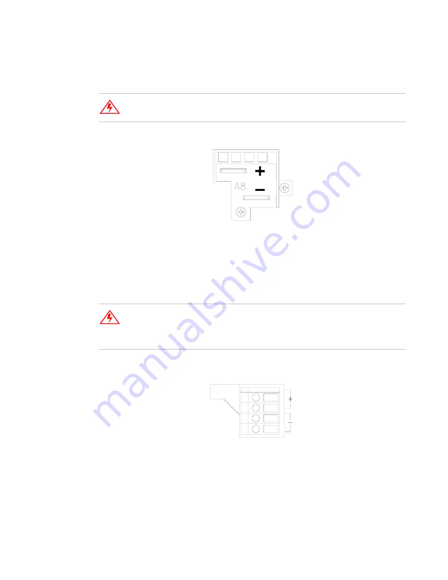
Connectors
Low Voltage Models
Equipped with positive and negative busbars. The busbars
are offset to facilitate load cable connections.
.
Figure 1.4
Output Busbars - note polarity markings
(Low Voltage Models)
High Voltage Models
High voltage models are equipped with a 4-terminal output
block. The top two are positive terminals whereas the lower two are negative. Screw
clamps are used to secure load connections.
Figure 1.5
Output Terminal - note polarity markings
(High Voltage Models)
WARNING
Disconnect the AC input before making any connections to the unit.
WARNING
Disconnect the AC input before making any connections. Lethal voltages may be
present at the output terminals for up to 15 seconds after the AC power has been
removed.
Summary of Contents for XPD 120-4.5
Page 2: ......
Page 3: ...Operating Manual for XPD Series Programmable DC Power Supply...
Page 50: ...Section 3 Local Operation User Diagnostics 48 Operating Manual for XPD Series Power Supply...
Page 54: ...Section 4 Remote Operation Status Flags 52 Operating Manual for XPD Series Power Supply...
Page 55: ......


