3
not change the pitch any further. This limita-
tion does not include the pitch cv v/oct in-
put which is handled by a separate precision
A/D converter.
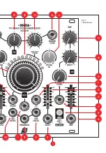
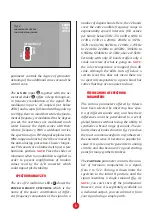
The big, central partials knob
6
limits the
spectrum of the signal to a specific number of
harmonic partials, from 1 to 512 per voice.
This limit can also be controlled by CV using
the jack below
7
. Note that the response
appears to be stepped, especially at the be-
ginning of the range, because it causes con-
secutive partials to be turned on and off. At
the minimum position, only the fundamental
frequency is audible. Also note that due to au-
tomatic volume compensation, lower frequen-
cies become quieter as higher components are
added to the spectrum.
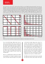
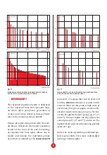
The red spectral tilt knob
8
controls how
quickly the amplitudes of consecutive partials
decrease with frequency. At the middle posi-
tion, partials decrease slowly, similar to the
spectrum of a saw wave. At the minimum po-
sition, the decrease is so rapid that mostly the
fundamental is audible. At the maximum posi-
tion, the amplitude spectrum is very flat (if no
additional comb response is engaged), which
results in a buzzy, narrow pulse waveform.
This parameter can be also controlled by ex-
ternal CV (±5V) via the dedicated jack
9
.
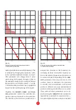
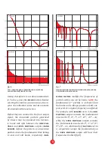
The three knobs near the right edge of the
panel control a comb-like frequency response
that is imposed on the spectrum. Note there is
no time-domain filtering applied to the signal
(which would involve a significant delay for
certain settings), instead, a frequency-domain
shaping function is applied to the amplitude
of each harmonic partial. The density knob
10
controls how dense the notches of the comb
are: from zero (no notches at all) through
moderate (just a few notches) to a maximum
density of 256, where each second partial is fil-
tered out (assuming minimum warp setting).
This parameter can be controlled by external
CV via the dedicated jack
11
that accepts
±5V, and is scaled by the slider potentiometer
above
12
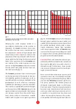
. The warp knob
13
controls the
uniformity of the comb response: from linear,
where notches are equidistant in frequency
(like in a classic flanger), up to a very nonlin-
ear response, where notches are very dense
at the bottom of the spectrum and become
more distant for higher overtones (similar to
a phaser effect). This parameter can also be
controlled by CV via the dedicated jack
14
that accepts ±5V, and is scaled by the slider
potentiometer above
15
. The peaking knob
16
controls the shape of the comb response:
from narrow notches (at the minimum posi-
tion) through moderate up to wide notches
with narrow peaks in the response (at the
maximum position). This parameter can be
controlled by a ±5V CV via the jack below
17
.
tension
18
is a very important and sensitive
parameter that determines whether the sinu-
soidal partials generated by Odessa adhere to
a harmonic pattern wherein frequencies are
strictly integer multiples of the fundamental
frequency. There is a little dead zone in the
central position of this knob that helps to set
it to zero. With tension set to sharp (above
the middle), partials are more spread apart so
that their frequencies increase more quickly
than with a linear law (e.g. the harmonic se-
ries) and the spectrum becomes sparse. With
tension set to flat (below middle), partials
are more condensed so that their frequencies
increase slowly and create a dense non-har-
monic cluster that may resemble noise. This
parameter can be controlled by a ±5V CV via
the jack below
19
.


