background image

15

5)


Correct amperage and travel speed 

are important and relevant to material 

thickness and are correct when sparks 

are exiting from the work piece.

If sparks are spraying up from the work 

piece there is insufficient amps selected 

or the travel speed is too fast.

6)


To finish the cutting release the torch 

switch.  The air flow will continue for 30 

seconds to cool the torch head.

2)


Connect the Earth Clamp securely to 

the work piece or the work bench.

3) 

Place and hold the torch vertical at the 

edge of the plate

4)


Pull the trigger to energise the pilot 

arc. The cutting arc will start when the 

nozzle is moved closer to the edge of 

the work piece. When the cutting arc has 

cut through the edge of the plate start 

moving evenly in the direction you wish 

to cut,

1)

 Wear your safety gear. Generally you want the 

same type of protective gear as when welding. 

Plasma has high arc voltage if the job or bench is 

wet and you place your hand or arm on it you can 

become part of the circuit and receive a shock, be 

sure you are wearing leather gloves, Full length 

pants and covered shoes, Wear eye protection a 

#5 shade is the minimum eye protection with other 

shades required


depending on amperage. A face 

shield is also recommended,

Operating procedure using the Stand Off Guide mounted to SC80 torch.


The feet of the standoff guide are placed on the cutting surface. This maintains an 


optimal 2mm standoff distance between the plasma cutting tip and the work, this is 


especially suitable if your hands are unsteady, or if you wish to use a straight edge 

guide or pattern guide. It also helps extend tip life.

Cut Quality

A clean cut depends on several factors:  

● 

amperage 

● 

travel speed 

● 

tip height & position  

● 

tip and electrode quality 

● 

air pressure and quality 

● 

technique

The best quality cut will be produced when all these variables are set correctly for the material thickness 

and type of material being cut. 


Poor quality cut

Good quality cut

Operating Procedure & Techniques 

for PLASMA Cutting

Summary of Contents for RAZOR CUT 45 PFC

Page 1: ...YEAR MACHINE WARRANTY 3 3 XA RZCUT45PFC K Operating Manual...

Page 2: ...he future RAZORCUT Plasma Cutters are manufactured and compliant with CAN CSA E60974 1 ANSI IEC 60974 1 AS NZ60974 1 guaranteeing you electrical safety and performance Air quality Good air quality is...

Page 3: ...escriptions 9 Power Installation 10 Set Up and Operating Procedure 11 Control panel 12 14 Plasma Cutting Procedure Techniques 15 18 SC40 Plasma Torch Parts Breakdown 19 Trouble Shooting 20 REGISTER YO...

Page 4: ...r cable for wear and tear replace the cable immediately if damaged bare wiring is dangerous and can kill Do not use damaged under sized or badly joined cables Do not drape cables over your body We rec...

Page 5: ...r can explode Because gas cylinders are normally part of the welding cutting process be sure to treat them carefully CYLINDERS can explode if damaged Protect gas cylinders from excessive heat mechanic...

Page 6: ...er table This equipment is of automatic voltage compensation which enables the maintaining of the voltage range within the given range In case that the voltage of input power supply amperage exceeds t...

Page 7: ...aterial such as hafnium and cerium This insert erodes with use also the nozzle orifice will erode with use Quality of the air used is paramount to longer life of electrodes and nozzles in short clean...

Page 8: ...asy to operate With its exceptional performance reliability and ease of use the RAZOR CUT45 is an excellent investment for anyone in need of a high quality plasma cutting machine Whether you re a prof...

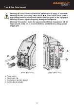
Page 9: ...may damage the equipment Warning This product meets the requirements of Class A equipment in EMC requirements and is not to be connected to a residential low voltage power supply grid 5 1 External int...

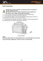
Page 10: ...larger cross sectional area to reduce the voltage drop 3x2 5mm2 or more is recommended Page 13 5 2 Power installation Warning The electrical connection of equipment shall be carried out by suitably q...

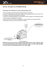
Page 11: ...tage drop due to the cable length Compressed air Page 13 5 2 Power installation Warning The electrical connection of equipment shall be carried out by suitably qualified personnel Warning All connecti...

Page 12: ...nd indicators 6 2 Display of parameters and error codes 1 Electric current configuration 2 When the factory settings are restored the countdown is displayed 3 In user mode the parameter settings are d...

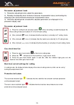
Page 13: ...Press the gas check button while not in cutting state 2 When the indicator is lit the machine is in gas check mode 3 Press the gas check button again or wait 20s After the indicator light goes out ma...

Page 14: ...that time to exit the countdown without entering engineer mode 3 Engineer mode F01 Standby time selection 0 5 10 or 15 unit is min 0 means that the standby function is not enabled F02 Input over volt...

Page 15: ...e job or bench is wet and you place your hand or arm on it you can become part of the circuit and receive a shock be sure you are wearing leather gloves Full length pants and covered shoes Wear eye pr...

Page 16: ...d the extent of the bevel of the cut The easiest way to reduce bevel is by cutting at the proper speed and height for the material and amperage that is being cut Correct torch height and square to the...

Page 17: ...ir supply is absolutely critical to quality plasma cuts and longevity of consumable parts As a minimum be sure to drain the receiver tank on the air compressor at least daily Most air plasma systems f...

Page 18: ...then push the electrode up and down for 10 20 times Remove the excess grease before assembling the torch Torch Head Electrode Holder Lubrication Apply in case of sticking or start stop is delayed Appy...

Page 19: ...Tip 0 9mm Cross Groove 12 SC8026 10 Contact Cutting Tip 1 0 mm 40 50A SC8026 11 Contact Cutting Tip 1 1 mm 50 60A SC8026 12 Contact Cutting Tip 1 2 mm 60 70A SC8026 13 Contact Cutting Tip 1 3 mm 70 80...

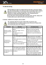
Page 20: ...uit is damaged Turn off the gas check function or wait 20s to exit automatically Check the torch trigger circuit Reconnect the compressed air Replace or repair the mainboard The pilot arc is discontin...

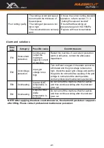
Page 21: ...epartment E32 Overvoltage protection Input grid voltage is too high Turn it off and on again If the alarm cannot be eliminated and the grid voltage remains too high check the power grid voltage and wa...

Page 22: ...imes of the machine so as to lengthen service life of the machines Period Maintenance item Daily examination Check the condition of the machine mains cables welding or cutting cables and connections C...

Page 23: ...23 Notes...

Page 24: ...24 Esseti New Zealand Limited PO Box 4189 Palmerston North 4442 Phone 06 355 1103 Fax 06 354 2437 Email sales esseti co nz www esseti co nz Xcel Arc Esseti NZ LTD 2023 New Zealand Limited...

Reviews: