XE210C Hydraulic Excavator
Operating and Maintenance Manual
118
the tank:
XE210C:220L.
XE230,XE260C
:
240L.
i)
Remove the drain plug to make the hydraulic oil discharged.
j)
Take out the components of oil suction filter and hanger rod.
k)
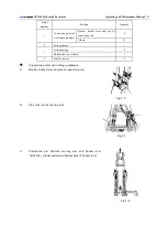
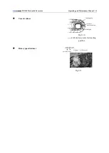
Clean inner sides of filter and oil tank. In case of replacing the filter,
attach a new filter to the hanger rod as shown in right figure.
l)
Attach the components of filter and hanger rod, and ensure the filter
is correctly fixed on the outlet.
m)
Replace the oil filter of hydraulic oil tank (refer to “List of
Maintenance Periods”).
n)
Clean, attach and tighten the drain plug.
o)
Fill the hydraulic oil up to its level between the marks of level meter.
p)
Attach the oil tank cover, and ensure the components of filter and
hanger rod are in correct positions.
Important: in case of starting the engine without oil in hydraulic pump, it will
damage the hydraulic pump.
q)
Remove the air bleed plug from the top of hydraulic pump.
r)
Fill up the hydraulic pump with hydraulic oil through the hole of air bleed
plug.
s)
Attach the air bleed plug.
t)
Start the engine and run it at low speed and empty load. Hang “No
Operation” nameplate to the safety locking rod, and ensure the safety
locking rod in LOCK (lock) position.
u)
Loosen the air bleed plug slowly to discharge the accumulated air. When the flow of air stops and the
oil is discharged out of the plug hole, tighten the plug.
v)
Run the engine at low speed and empty load, and actuate the control lever slowly or stably for 15
minutes to discharge the air out of the hydraulic system.
w)
Retract the state positioner fully with a bucket rod hydraulic cylinder, and stretch it out fully with a
bucket hydraulic cylinder.
x)
Stop the engine as per the shutdown steps of engine (P20).
y)
Pull the safety locking rod to LOCK (lock).
z)
Check the level meter of hydraulic oil tank. If necessary, open the oil tank cover to add in the oil.
●
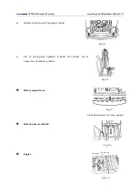
Drain the dirt reserve tank of fuel tank.
a)
Drain the dirt reserve tank of fuel tank every day.
b)
For the convenience of access, rotate the upper car by 90°, and park the
machine on flat ground.
c)
Stop the engine as per the shutdown steps of engine (P19).
Important: if the shutdown steps of engine are incorrect, the turbo
Fig.2-33
3
-
Components of oil suction filter
and hanger rod
Fig.2-35
1
-
Drain ball valve
2
-
Fuel ball valve
Fig.2-34
4
-
Air bleed plug


