background image

XZ320 Horizontal Directional Drill                                                                        Usage Manual


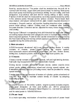
fixed  by  anchor  device.  The  probe  shall  be  installed  into  the  drill  bit  to 
connect drill bit body, auger stem and power head for drilling.  Mud pump 
also  shall  pump  mud  during synchronous drilling  for soil cutting  and  heat 
dissipation  of  protective  wall  and  drill  bit  during  drilling  or  back  towing. 
Position of drill bit shall be measured by receiving signals issued by probe 

in  the  wireless  probe  through  earth’s  surface  receiver.  Power  head  shall 

stop  rotation  and  adjust  inclined  drill  bit  plate  toward  required  direction  if 
necessary.  Ground  receiver  will  monitor  feeding  direction  when  pushing 
power  head  without  rotation.  Drilling  shall  be  continued  after  defining 
accurate direction. Direction can be adjusted for many times during drilling 
until ending. 

Pipe layout: Different re-expanding hole drill bits shall be used after drilling 
according to pipe diameter and category for once or multiple back drilling to 
reach required aperture. Power divider can be connected to set pipe during 
the final back drilling and towing until all pipes are positioned. Mud shall be 
supplied during the entire process. 

2. Main structure 

XZ320  horizontal  directional  drill  is  an  integral  drilling  device.  It  mainly 
consists  of  chassis,  power  head,  drilling  rig,  engine  system, 
semi-automatic access assembly of auger stem, jaw vice, anchor device, 
drilling tool, hydraulic system, electric system and mud system, etc. 

2.1 Chassis 

Chassis mainly consists of automatic chassis, left and right driving devices. 
Hydraulic leg is supplied in the rear of automatic chassis. 

Driving  device  consists  of  crawler  tension  device,  rubber  crawler,  drive 
wheel,  guide  wheel,  supporting  wheel  and  driving  speed  reducer,  etc. 
Embedded planetary reducer (including motor) shall be provided for driving 
speed reducer. 

Crawler tension device consists of tension oil cylinder, guide wheel and oil 
cup,  etc.  It  is  used  to  maintain  certain  tensity  of  crawler  by  adopting 
lubricating grease. 

2.2 Engine system 

As  power  source  of  the  entire  system,  engine  system  includes  engine, 
water  heat  dissipater,  air  filter  and  muffler,  etc.  D6114  pressurized 
water-cooled engine of Shanghai Diesel Engine Co., Ltd shall be selected 
and its rated power is 140kW/2300r/min. 

2.3 Power head 

As  a  main  operating  mechanism  of  machine,  output  axle  of  power  head 

top-stm.ru

Summary of Contents for XZ320

Page 1: ...t o p s t m r u ...

Page 2: ... detector etc Warning Reconfiguration may cause dangers without manufacturer s permit before usage Please consult to manufacturer or designated dealer before reconfiguration or manufacturer has no responsibility for any consequence caused by impermissible reconfiguration Note XZ320 horizontal directional drills have gained many patent licenses issued by the State Intellectual Property Office SIPO ...

Page 3: ...principle and structure 5 Safety requirements 16 Usage and operation 21 Lubrication repair and maintenance 45 Transportation storage and protection 52 Appendix A Mud consumption 56 Appendix B Nozzle flow 57 Appendix C The maximum diameter and length of tow pipe 58 t o p s t m r u ...

Page 4: ...ow comprehensive expense and high economic and social benefits 1 Designation XZ 320 Pull back force 320kN Horizontal directional drill 2 Applicable scope It is suitable to sandy soil clay and pebble etc Most of non hard rocky zones in China can be constructed and ambient temperature is between 10 and 45 3 Product characteristics 3 1 Reliable power Total power is 140kW for water cooled vortex press...

Page 5: ...e construction cost as well as rupture risk of auger stem 3 5 Rubber crawler Hydraulic rubber crawler has the minimum damage to side pavement lawn and beauty spots 3 6 Optional hydraulic anchor devices Hydraulic drive with high efficiency can be selected to position drills quickly reliably and stably 3 7 Optional auxiliary loading unloading device of auger stem Auxiliary loading unloading device o...

Page 6: ...XZ320 Horizontal Directional Drill Usage Manual 3 II Structure Properties and Main Parameters 1 Please refer to Figure 1 for outline dimension of drills Figure 1 Outline drawing of drill t o p s t m r u ...

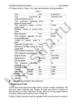
Page 7: ... maximum mud flow L min 320 The maximum mud pressure MPa 8 Engine model D6114ZG Rated power kW r min 140 2300 Driving speed km h 3 The maximum climbing gradient 30 Machine weight kg 10500 Outline dimension under transportation status Length mm 7100 Width mm 2250 Height mm 2450 III Operating principle and structure 1 Operating principle XZ320 horizontal directional drills mainly consist of upper di...

Page 8: ...towing until all pipes are positioned Mud shall be supplied during the entire process 2 Main structure XZ320 horizontal directional drill is an integral drilling device It mainly consists of chassis power head drilling rig engine system semi automatic access assembly of auger stem jaw vice anchor device drilling tool hydraulic system electric system and mud system etc 2 1 Chassis Chassis mainly co...

Page 9: ...ng service life of auger stem 2 7 Optional anchor devices Ground anchor is used for anchorage of the entire machine It is located in the front end to increase stability It shall be pressurized by oil cylinder for drilling in out of anchor rod driven by low speed and large torque motor 2 8 Vehicle mounted mud system Large flow mud pump of 320L min shall be adopted for vehicle mounted mud system Hor...

Page 10: ...per low Hourly rotation speed list To record operating hours and current rotation speed of power generator Voltmeter The list is to measure voltage of electric system Jamming alarm of hydraulic filter Indicator lamp is on to indicate that oil filter shall be cleaned due to jamming 2 8 2 Mud pump control Mud pump switch is used to control mud pump and mud pressure can be displayed by mud pressure g...

Page 11: ...ing drilling or back towing if main axle is not connected to auger stem Mud pump will stop operation automatically when using high speed push pull function High speed rotation of power head shall be controlled by manual valve on power head box Manipulation rods of the valve shall be placed in different positions to guarantee different rotation speed of power head Please do not use high speed rotat...

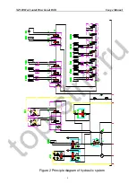
Page 12: ...XZ320 Horizontal Directional Drill Usage Manual 9 Figure 2 Principle diagram of hydraulic system t o p s t m r u ...

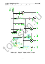
Page 13: ...XZ320 Horizontal Directional Drill Usage Manual 10 2 9 Principle of electric system shown in Figure 3 Figure 3 The 1st schematic diagram of electric system t o p s t m r u ...

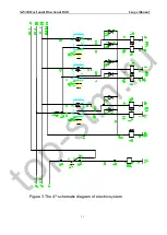
Page 14: ...XZ320 Horizontal Directional Drill Usage Manual 11 Figure 3 The 2nd schematic diagram of electric system t o p s t m r u ...

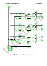
Page 15: ...XZ320 Horizontal Directional Drill Usage Manual 12 Figure 3 The 3rd schematic diagram of electric system t o p s t m r u ...

Page 16: ...XZ320 Horizontal Directional Drill Usage Manual 13 Figure 3 The 4th schematic diagram of electric system t o p s t m r u ...

Page 17: ...XZ320 Horizontal Directional Drill Usage Manual 14 Figure 3 The 5th schematic diagram of electric system t o p s t m r u ...

Page 18: ...XZ320 Horizontal Directional Drill Usage Manual 15 Figure 3 The 6th schematic diagram of electric system t o p s t m r u ...

Page 19: ... the equipment 1 1 Only trained operators with rich experience can operate the drill Be sure to read the manual and accept operation training before operation 1 2 Please contact local utility pipe company before construction for assistance with position detection and mark of original underground pipes and cables along the route Please contact relevant departments in a timely manner if pipes are da...

Page 20: ...s to convey other chemicals liquid or gas 4 Electric shock knowledge 4 1 Current will be conveyed to underground by various ways besides channel of the minimum resistance 4 2 Current also can be conveyed to equipment by cables of auger stem hose and machine 4 3 Casualty or death may be caused by low voltage current 4 4 Electric shock shall be assumed under following circumstances 4 4 1 Power failu...

Page 21: ...es are broken by drilling 7 1 Close the drill and contact local utility pipeline department instantly 7 2 Do not look broken ends of optic fibers or unknown cables directly into our eyes to avoid impairment of vision 8 Operation when tap water pipes are broken by drilling 8 1 Close the drill and contact local utility pipeline department instantly 8 2 Anybody is strictly prohibited to access the da...

Page 22: ...wires shall be exposed by manual excavation and bore track shall be traced by probe carefully 9 2 2 3 Gas supply cutoff during construction Fuel gas department shall inspect pipes before restoring gas supply 9 2 3 Other site protection measures Different methods may be used to prevent us from other underground dangerous articles Please contact responsible person of dangerous articles to define pro...

Page 23: ...o possible casualty even death by touching electrified body Keep far away from it due to possible severe casualty caused by movable parts Use suitable process procedure and facility or keep far away from it due to possible casualty even death caused by protrusion t o p s t m r u ...

Page 24: ...zontal Directional Drill 21 V Usage and operation 1 Functional instructions of switch handle or instrument 1 1 Please refer to Figure 4 for operation panel of left console and Table 2 for detailed functions t o p s t m r u ...

Page 25: ...temperature alarm Temperature of hydraulic oil is super high if indicator lamp is on 9 Water temperature alarm of engine Cooling liquid temperature of engine is super high if indicator lamp is on 10 High speed driving switch Driving speed of drill will be doubled by pressing the switch 11 Loudspeaker switch To control operation and shutdown of loudspeaker 12 Rotation lamp switch To control opening...

Page 26: ...nual of XZ320 Horizontal Directional Drill 23 1 2 Please refer to Figure 5 for operation panel of right console and Table 3 for detailed functions Figure 5 Operation panel of right console t o p s t m r u ...

Page 27: ... 6 Post jaw vice switch To control clamping or loosening of post jaw vice 7 Pushing handle To control push pull of auger stem 8 Push pull pressure gauge To display pressure of push pull motor 9 Rotary pressure gauge To display pressure of rotary motor of power head 10 Installation plate of guide instrument Guide instrument shall be installed here 11 Mud pressure gauge To display pressure of mud sy...

Page 28: ...uel oil gauge To display fuel oil quantity 5 Water temperature gauge To display temperature of cooling liquid of engine 6 Voltmeter To display system voltage 7 Hourly rotation speed list of engine To display rotation speed and working hours of engine 8 Control handle of accelerator To control engine accelerator 1 4 Please refer to Figure 7 for operation panel of post console and refer to Table 5 f...

Page 29: ... left crawler 7 Driving acceleration switch To control driving speed Note Driving acceleration position must be in non acceleration position after finishing movable machines or power head can not be pushed or pulled 2 Preparation 2 1 Data collection Successful construction begins from bore and existing documents of the project and construction site shall be read firstly 2 1 1 Contact utility pipel...

Page 30: ...c of the system 2 2 10 Select points and collect soil samples along bore track to define drill bits for drilling and re expanding 2 3 Verification of dangerous articles Please refer to Safety Protection for verification of underground dangerous articles and division of site category Note Use equipment by abiding by operation regulations accurately and maintain necessary safety protection facilitie...

Page 31: ... notify engineer of the minimum perforation angle bending extreme of auger stem back tow materials length of auger stem and positions of various underground pipelines Four parameters shall be considered before drilling for simple bore It is suggested to consider bending extreme of auger stem perforation angle the minimum angle buildup distance and the minimum depth Suggested bending extreme shall ...

Page 32: ... if angle buildup distance is excessively small The minimum angle buildup distance can be defined by known perforation angle according to bore depth requirements to the ground 2 5 3 The minimum hole location depth Auger stem must be bent stably so bore depth to the ground under horizontal status shall be defined by perforation angle and bending extreme of auger stem Depth is in inverse proportion ...

Page 33: ... 6 5 9 Bentonite polymerizer water processor and other additives 2 6 5 10 Fuse 2 6 5 11 Re expanding probes rotary connectors and back tow facilities 2 6 5 12 Hose and water gun for washing 2 6 5 13 Pipe tape 2 6 5 14 Thread dope and brush 2 6 5 15 Insulation shoes and gloves 2 6 5 16 Tally book and pen 2 7 Site preparation Note Such sites shall be classified into power type site if there is any d...

Page 34: ...artup button then start up the engine Please refer to engine manual for startup and usage of engine 2 8 3 Low speed no load operation for 5 minutes is required after engine startup for pre heating 2 9 Drill positioning 2 9 1 Drill shall be positioned according to soil insertion pint 2 9 2 Rack shall be inclined to reach required soil insertion angle according to demand 2 9 3 Post leg shall be lowe...

Page 35: ...aw vice 2 10 2 4 Lubricate the connector 2 10 2 5 Connector shall be tightened by machine torque 2 10 3 Connect probe container tube 2 10 3 1 Drilling rig shall be placed in the front jaw vice 2 10 3 2 Close the jaw vice 2 10 3 3 Connector shall be tightened by machine torque 2 10 4 Optional connection of drilling rig by combination pliers 2 10 4 1 Drilling tool shall be connected to the 1st auger...

Page 36: ...all be tightened for 2 circles inversely to release pressure then components of combination pliers shall be detached 2 10 5 Marking on process shown in Figure 12 Figure 12 Marking on processes 2 10 5 1 Slag shall be removed from wrench and connector thoroughly 2 10 5 2 A line shall be marked to divide 2 ends of partition line 2 10 5 3 The 2nd line shall be marked to be about 9 5mm away from the 1s...

Page 37: ...le connector is closed to threads of auger stem 2 10 6 5 2 Power head shall continue to move forward until auger stem is inserted into main axle connector 2 10 6 5 3 Power head shall move forward until auger stem terminal is aligned to thread of buffer rod 2 10 6 5 4 Use the pushing rotation controller to rotate the main axle and auger stem slowly then install them to threads of the buffer rod 2 1...

Page 38: ...uger stem will rotate positively and shackle when power head moves backward 3 2 Drilling the 1st rod 3 2 1 System startup 3 2 1 1 Start up drill and mud device to pre heat 2 engines Please refer to usage manual of mud mixing system for operation IMPORTANT Be sure that mixed liquid can meet drilling conditions Auger stems drilling rigs and short connectors of different factories can not be mixed 3 ...

Page 39: ...o be close to front jaw vice 2 and close the mud pump if connector is between jaw vices Figure 14 Holding the auger stem 3 3 2 1 Loosen the manipulation rod when auger stem connector in main axle thread is between front jaw vice 2 and post jaw vice 1 3 3 2 2 Start up the front jaw vice 2 until auger stem is clamped with increased pressure 3 3 2 3 Main axle shall be rotated counter clockwise until ...

Page 40: ...er 3 4 5 Rotate lifting device switch for declination Note Be sure that lifting device of auger stem is in the lowest position before pushing power head forward Guarantee sufficient free motion distance between power head and carriage during loading unloading of auger stem 3 5 Pressure the charging mud pump switch so that auger stem is full of mud with increased mud pressure Note Adjust speed cont...

Page 41: ...on pushing distance 4 1 3 2 All machines shall be corrected gradually Please refer to bending extreme of auger stem Excessive correction may damage auger stem and cause difficult drilling and back towing so it is required to straighten as early as possible for correction 4 1 3 3 Do not push the entire auger stem into the ground if it does not rotate because auger stem may be damaged by exceeding t...

Page 42: ... river bed because pipes may float due to super small distance In the meanwhile guide hole is difficult to construct due to small distance of river bottom and complex soil quality Guide hole shall be at least 4m away from road base when passing across railway or highway Depth shall be increased if expanding diameter is larger Various conditions on the site shall be collected completely when passin...

Page 43: ...e far away from them Back towing is required firstly until drill bit begins to enter into the soil then it shall be rotated slowly 7 1 Re expanding steps 7 1 1 Selection of re expanding device Selection of re expanding drill bit may be influenced by dimension of pivot hole back towing materials and soil conditions so please contact dealer or factory for details Ideal final bore aperture is approxi...

Page 44: ...ing hole and outer diameter of drawn materials shall be defined and required mud consumption can be known according to Appendix A For instance a re expanding hole of 15 2 cm namely 6 inches needs at least 19L m 1 47 gallon foot while a back towing material of 7 6cm needs at least 5L m 0 37 gallon foot 7 2 2 2 Mud consumption required by every foot or meter of re expanding can be calculated by diff...

Page 45: ...an return to its original position 8 3 Separate the front connector 8 3 1 Clamp the auger stem by post jaw vice 8 3 2 Rotate the power head counter clockwise and loosen the connecting thread 8 3 3 Rotate auxiliary loading unloading device of auger stem and clamp the auger stem so that post jaw vice can loosen the auger stem 8 3 4 Rotate the main axle slowly and counter clockwise move power head ba...

Page 46: ...s 9 1 2 Jamming of bricks or stones in the soil Loosen the torque and rotate the drill bit for slow expanding Jamming of large stone or concrete in the soil Strive to retract the drill bit and move drill for re drilling or excavate stones for continued expanding Do not operate forcefully or auger stem may be broken and drill is lost in the hole 9 1 3 Slow down expanding speed and increase mud cons...

Page 47: ...solidfree protective wall can be adopted to reduce contact between hole wall and water and reduce water loss Expanding diameter can be added with multiple borehole cleaning to avoid stratum expansion and protrusion to set pipes effectively 9 5 Mud loss Mud in loose backfill soil layers such as sandy silt clay sand layers and soft soil layers on the bottom of river bed will lose from the hole due t...

Page 48: ...n mud shall be pumped for 10 minutes after re drilling so that mud can exit the hole for back towing and pipe layout 9 8 Expanding efficiency Torque and rotation speed of drill are in direct proportion of expanding efficiency Expanding efficiency relates to expanding soil layer drill bit mud quality and mud consumption directly under rated torque and rotation speed of drill Clarify soil layer stru...

Page 49: ...ted by bulldozer and excavator for re borehole cleaning and pipe layout 10 Add antifreeze fluid into the drill Drill can operate in the night under low temperature by using approved antifreeze fluid Steps to add antifreeze fluid 10 1 Connect one end to mud pump by a hole and the other end shall be placed into the antifreeze fluid 10 2 Adjust the mud pump to the minimum flow gear 10 3 Start up the ...

Page 50: ... damaged Sharp turn shall be evaded with super low speed for operation under following conditions 1 2 1 Grit road 1 2 2 Stone road 1 2 3 Steps 1 3 Warning 1 3 1 Driver shall drive it slowly and carefully on the rough pavement to avoid damage to wheel and crawler 1 3 2 Strive to avoid abrasion between rubber crawler and cement wall during driving to avoid rim crack of rubber crawler 1 4 Driving tec...

Page 51: ...al Directional Drill 48 shall be removed instantly or service life of crawler may be damaged Warning Rubber crawler damaged by improper operation is not within regulated scope of three warranties of the machine t o p s t m r u ...

Page 52: ...ngine maintenance shown in Table 7 Table 7 Engine maintenance Task Period hour Oil product Inspection of machine oil 10 Please refer to engine operation instructions Replacement of machine oil and filter for the 1st time 50 Please refer to engine operation instructions Replacement of machine oil and filter 100 Please refer to engine operation instructions 2 2 Sliding rack lubrication shown in Tabl...

Page 53: ...MALA EP150 Caltexoils Meropa 150 2 4 Maintenance of hydraulic system shown in Table 10 Table 10 Maintenance of hydraulic system Item Hour Hydraulic oil Inspection of hydraulic oil 10 L HM46 Replacement of oil filter for the 1st time 50 Replacement of oil filter 250 Replacement of hydraulic oil and filter core 1000 2 5 Maintenance of mud pump shown in Table 11 Table 11 Maintenance of mud pump Lubri...

Page 54: ... 50 Inspection of storage battery Belt inspection Replacement of oil filter for the 1st time 100 Inspection of drilling tool 250 Replacement of oil filter 2000 Washing cooling system If necessary Replacement of air filter Replacement of sliding plate of power head or clamp holder Replacement of wearing parts such as short connector of auger stem power divider re expander and torque sleeve etc Muff...

Page 55: ...f there is leakage or loose connection or not 2 8 3 Engine belt The transmission belt drives AC power generator cooling fan and water pump Operating conditions of tension device and idle pulley shall be inspected every 50 hours to check if belt is in accurate position with abrasion or not 2 8 4 Radiator Check if there are sundries weeds or sundries or not by inspection every 25 hours It shall be c...

Page 56: ...ulley Check if power head pulley is abraded or not with replacement if necessary It can be adjusted by removing adjustment gaskets in phases Removed gaskets shall be reserved and installed again during pulley replacement 2 9 Maintenance of filter core shown in Table 14 Table 14 Filter maintenance Item Period hour Replacement of machine oil filter Shown in Lubrication chapter Replacement of fuel oi...

Page 57: ...ity of feeding chain Tensity of feeding chain shall be adjusted as follows if necessary 2 10 2 1 Move power head to the rear end of sliding rack 2 10 2 2 Loosen connecting rod nut below head support of drilling frame 2 10 2 3 Screw down nuts clockwise to tighten chain then lock it by nuts 2 11 Gear box and motor Inspect gear box and motor every 10 hours to check if there is leakage or not 2 12 Mai...

Page 58: ...ded by owner without relying on crane Please refer to Figure 15 for support dimension Figure 15 Support dimension diagram In the figure h refers to height of transportation platform of vehicle to the ground α 16 7 namely l 3 3Xh Support shall bear weight of the entire drill with certain safety coefficient 2 Drill transportation Warning Drill operator or other persons can not stay on the drill to a...

Page 59: ...portation position 2 6 Rotate the guide rail to the horizontal position 2 7 Engine shall operate with low speed so that drill can move to the tow truck or auto truck with low speed Warning Drill shall move forward during motion on the horizontal ground or downslope pavement and retreat during upslope or moving to tow truck to strengthen safety precaution measures and facilitate operation 2 8 Guara...

Page 60: ...Retract the key and power off main power switch then keep the key properly Short term storage Short term storage refers to storage period which does not exceed 2 months Drill shall be kept in a garage with excellent ventilation and it shall be far away from combustible explosive and volatile articles It must be covered by firm and durable coverage if there is no garage Please refer to engine usage...

Page 61: ...ring actual construction shall be larger than value in the list or construction may be invalid due to poor cooling or lubrication in the hole Diameter of re expanding drill bit or back towing pipe Gallon foot Liter meter 5 12 70 cm 1 02 12 67 5 5 13 97 cm 1 23 15 33 6 15 24 cm 1 47 18 24 6 5 16 51 cm 1 72 21 41 7 17 78 cm 2 24 83 7 5 19 05 cm 2 29 28 50 8 20 32 cm 2 61 32 43 8 5 21 59 cm 2 95 36 6...

Page 62: ...11 137 95 17 43 18 cm 11 79 146 44 17 5 44 45 cm 12 79 155 18 18 45 72 cm 13 22 164 17 18 5 46 99 cm 13 96 173 42 19 48 26 cm 14 73 182 92 19 5 49 53 cm 15 51 192 68 20 50 8 cm 16 32 202 68 20 5 52 07 cm 17 15 212 94 21 53 34 cm 17 99 223 46 21 5 54 61 cm 18 86 234 23 22 55 88 cm 19 75 245 25 22 5 57 15 cm 20 65 256 52 23 58 42 cm 21 58 268 05 23 5 59 69 cm 22 53 279 83 24 60 96 cm 23 5 291 86 24 ...

Page 63: ...e minimum mud flow per minute Please refer to Figure 16 for pressure and flow curve with different nozzle diameters Figure 16 Relation diagram of pressure and flow In Figure 15 A Flow of every nozzle Unit Liter minute B Nozzle pressure Unit Kilogram centimeter 2 C Nozzle diameter Unit Millimeter Appendix C The Maximum and Length of Tow Pipes Please refer to following list for the maximum operating...

Page 64: ... tow pipe or plastic tube Diameter of drill bit φ mm The maximum length of tow pipe m 63 1076 75 1068 90 1057 110 1038 125 1027 140 1006 160 982 200 927 225 891 250 853 315 756 400 636 500 514 630 392 800 281 1000 210 1200 205 Diameter of drill bit φ mm The maximum length of tow pipe m 152 840 159 785 168 730 173 715 180 675 194 655 203 644 219 558 245 525 273 494 299 470 325 447 351 425 377 407 4...

Page 65: ... Ltd 地址 中国 江苏 徐州经济开发区驮蓝山路 36 号 Add No 36 Tuolanshan Road Economic Developing zone Xuzhou JiangSu China 全国统一客服热线 Tel 400 110 9999 销售部电话 Tel 0516 87738167 87738169 87892612 传真 Fax 0516 87892627 103 104 109 服务处电话 Tel 0516 87892690 87738150 传真 Fax 0516 87738173 邮编 Postcode 221004 网址 http www xcmgjc com 2011 年 10 月版 t o p s t m r u ...

Reviews: