5
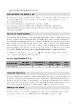
NOTE: ASOL-250P-WSR MODULES ARE “A” CLASS APPLICATION DEVICES. MAXIMUM
SYSTEM VOLTAGE 1000 VDC.
ASOL-250P-WSR series modules and most PV system components have a maximum system voltage rating of
1000 volts DC. Some grid feed in systems operate at or near this voltage rating. Like other polycrystalline solar
modules, the open circuit voltage of the ASOL-250P-WSR series modules increases as the ambient
temperature decreases. Maximum system voltage is computed as the sum of the open-circuit voltage of the
series-connected photovoltaic modules for the lowest expected ambient temperature. Temperature
coefficients, specific to the module of use, can be used to provide the most accurate prediction of module
voltage under temperature extremes
.
NOTE:
Install the maximum number of series for the ASOL-250P-WSR series modules so that the system
voltage is less than 1000 V. XDISC S.A. recommends to connect less than twenty modules in series to keep
safe voltage rate in the system.
XDISC S.A. does not recommend connecting modules in parallel configuration due to damage or destruction
of modules.
NOTE:
In normal conditions, PV modules may produce larger current and/or voltage than reported in the
standard test conditions. Therefore, when voltage evaluations for components, capacity of conductors, size of
fuses, and size of control systems connected to the module output are determined, multiply the values of
short- circuit current (I
sc
) and
open-circuit voltage (V
oc
) that are marked in ASOL-250P-WSR series modules by
the coefficient, 1.25.
Before installing your system, contact local authorities to determine the necessary permit, installation and
inspection requirements
.
INSTRUCTIONS ON CABLING
The modules are supplied ex works with a solar cable, 4 mm² including connector and an installation coupling
to the MC 4 system power socket
.
-
Ensure that the maximum system values for voltage and current are not exceeded.
-
When connecting modules in series ensure that the modules have the same current, the same alignment
and inclination.
-
When interconnecting the modules ensure that the maximum string voltage does not exceed the
maximum system voltage of the respective module type (for values refer to the data sheet of the
corresponding module).
-
Do not open the power socket.
-
Avoid large cable loops.
-
Ensure that the polarity is correct.
-
Use only suitable connectors (MC 4).
-
Use only a suitable solar cable with a correspondingly suitable conductor cross-section (min. 4 mm²,
copper).
-
Protect the cables against direct solar irradiation.
-
Before commissioning the overall system check that the cabling and the DC voltages are correct.
-
Fasten the cables with cable ties that are resistant to ultraviolet rays (e.g. to the mounting frame).


