background image


-


Ensure that the connectors are connected correctly. 

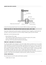
INSTRUCTIONS FOR GROUNDING 

The modules have to be grounded. Please observe the corresponding national regulations and standards. Due 
to ASOL-250P-WSR modules are framed and do not have specified point of grounding it is necessary to 
ground all installation system. 
Use one of the fastening holes in the construction to ground the module. 
Use a copper grounding conductor with a minimum diameter of 16 mm² (heat resistance 90 °C). 
When fastening the grounding conductor use a tooth lock washer so that the anodized layer of the 
construction is penetrated. 

ELECTRICAL SPECIFICATIONS 

The module electrical ratings are measured under Standard Test Conditions (STC) of 1 kW/m

2

 irradiance with 

an  AM  1.5  spectrum,  and  cell  temperature  of  25.  The  detailed  electrical  and  mechanical  characteristics  of 
ASOL-250P-WSR  crystalline  silicon  PV  modules  can  be  found  in  datasheet.  Main  electrical  characteristics  at 
STC also appear on each module label. The maximum system voltage for all module series is 1000 V. Under 
certain  conditions,  a  module  may  produce  more  current  or  voltage  than  its  Standard  Test  Conditions  rated 
power. Accordingly, when determining component ratings and capacities, the module short-circuit current at 
STC should be multiplied by 1.25, and a correction factor should be applied for the open-circuit voltage. 

An additional 1.25 multiplier for the short-circuit current (for a total of 1.56) for sizing conductors and fuses 
may be applicable, depending on your local regulations

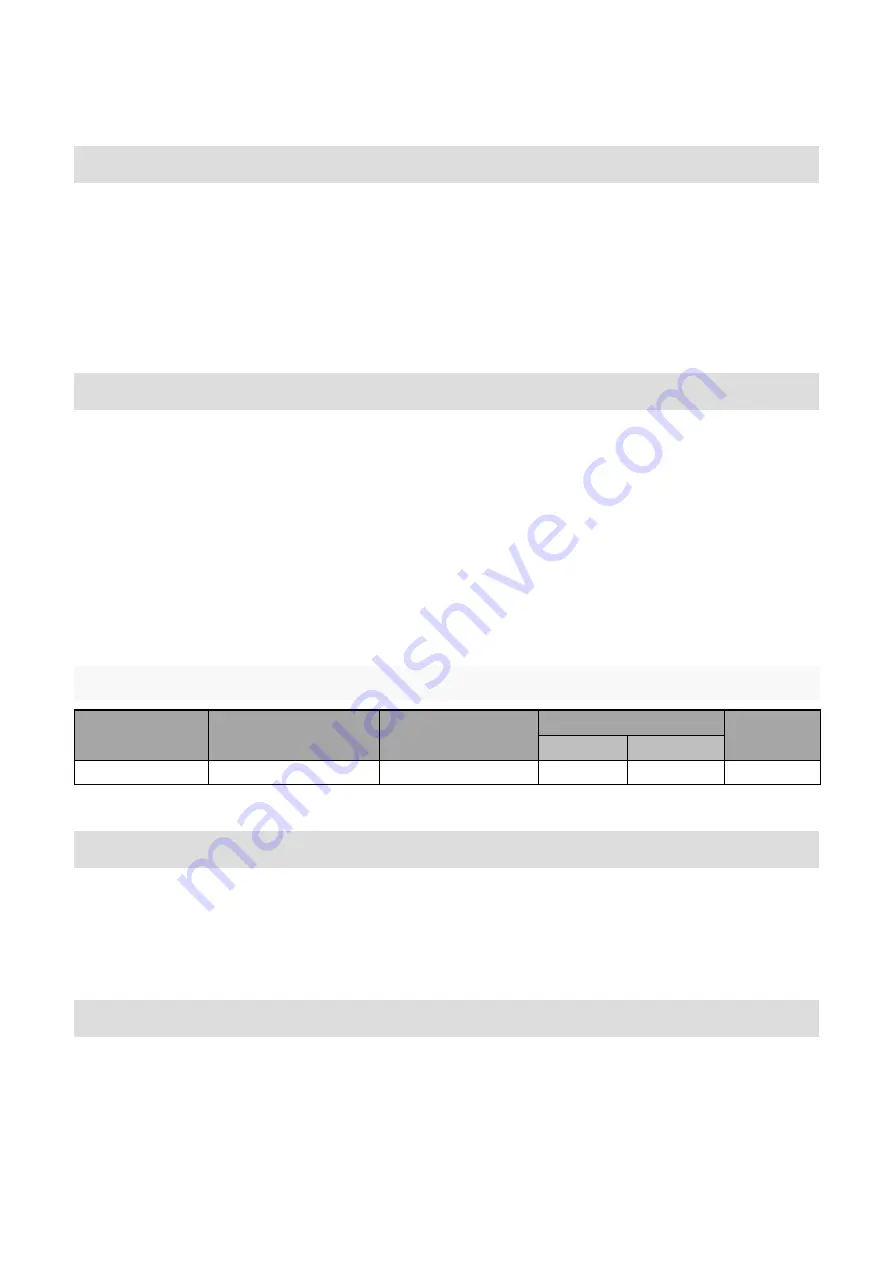
BY-PASS DIODE SPECIFICATIONS 

MODULE SERIES 

NUMBER OF 

BY-PASS DIODES 

NUMBER OF CELLS 

BY DIODES 

DIODE RATINGS 

DIODE 

TYPE 

VOLTAGE 

CURRENT 

ASOL-250P-WSR


20 

45V 

16 A 

Schottky 


LOCATION SELECTION 

The solar modules should be mounted in a location where they will receive maximum sunlight throughout the 
year. Modules facing 30 degrees away from true South (or North) will lose approximately 10 to 15 percent of 
their power output. If the module faces 60 degrees away from true South (or North), the power loss will be 20 
to 30 per cent. When choosing a site, avoid trees, buildings or obstructions which could cast shadows on the 
solar modules especially during the winter months when the arc of the sun is lowest over the horizon. 
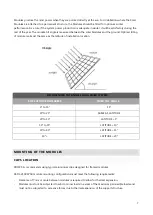
MODULE TILT ANGLE 

Modules connected in series should be installed at same orientation and angle. Different orientation or angle 
may cause loss of output power due to difference of amount of sunlight exposed to the module. 

Summary of Contents for ASOL-250P-WSR

Page 1: ...MOUNTING INSTRUCTION for PHOTOVOLTAIC MODULES Type ASOL 250P WSR ...

Page 2: ...UNDING 6 ELECTRICAL SPECIFICATIONS 6 By pass diode specifications 6 LOCATION SELECTION 6 MODULE TILT ANGLE 6 MOUNTING OF THE MODULES 7 Clips location 7 Mounting with screws 9 MAINTENANCE OF PHOTOVOLTAIC MODULES ASOL 250P WSR 9 Periodic cleaning of the module 9 Visual inspection 9 Connection and wiring controls 10 Manufacturer 10 ...

Page 3: ...d professional manner Electrical work should be performed by a qualified electrician WARNING This photovoltaic module produces electricity when exposed to the sun or other light sources The electrical hazard from the voltage and current of a single module is low However the voltage increases as modules are connected in series and the available current increases as modules are connected in parallel...

Page 4: ...uch the terminals with bare hands Use insulated tools when wiring to solar module terminals wear rubber gloves to eliminate shock or burn potential when wiring solar modules Regardless of whether you are working on a new or existing roof never allow the sheathing and metal parts to become wet Protect the sheathing and metal parts from rain during the installation Failure to do so may cause leaks W...

Page 5: ...for components capacity of conductors size of fuses and size of control systems connected to the module output are determined multiply the values of short circuit current Isc and open circuit voltage Voc that are marked in ASOL 250P WSR series modules by the coefficient 1 25 Before installing your system contact local authorities to determine the necessary permit installation and inspection requir...

Page 6: ...st Conditions rated power Accordingly when determining component ratings and capacities the module short circuit current at STC should be multiplied by 1 25 and a correction factor should be applied for the open circuit voltage An additional 1 25 multiplier for the short circuit current for a total of 1 56 for sizing conductors and fuses may be applicable depending on your local regulations BY PAS...

Page 7: ... location RECOMENDED TILT ANGLES FOR A FIXED SYSTEM SITE LATITUDE IN DEGREES FIXED TILT ANGLE 0 to 15 15 15 to 25 SAME AS LATITUDE 25 to 30 LATITUDE 5 30 to 35 LATITUDE 10 35 to 40 LATITUDE 15 40 LATITUDE 20 MOUNTING OF THE MODULES CLIPS LOCATION XDISC S A recommends using typical aluminium clips designed for framed modules ASOL 250P WSR module mounting configurations must meet the following requi...

Page 8: ...e mounted and must not cause any twist or stress to be placed on the module Modules should be secured to mounting structure using four aluminium at least 80 mm long module clips The retaining clips must each provide a minimum contact area of 10 mm x 80 mm The centre of mounting clips must be located on the long side of the module between 350 mm and 400 mm from the edge See following figure for all...

Page 9: ...d on the transparent cover of the module reduces its performance and can produce reverse effects similar to those produced by shading The problem can become serious in the case of industrial waste or waste caused by birds The intensity of the effects depends on the opaqueness of the residue The layers of dust that reduce the intensity of the sun are not dangerous and the reduction in power is not ...

Page 10: ... wiring Also check to be sure that mounting hardware is tight Loose connections will result in damage for array Do not touch live parts of cables and connectors Use appropriate safety equipment insulated tools insulating gloves etc when touching them Cover the front surface of the Module by an opaque or other material when repairing The ASOL 250P WSR modules when exposed to sunlight generate high ...

Reviews: