
Xena Networks ApS
2009-11
Page
3
INSTALLATION
STEPS
To install the C4-12 chassis, the following
steps must be completed:
Step 1:
Unpack the chassis.
Step 2:
Install the front handles.
Step 3:
Remove the top cover and hold-
down clamp.
Step 4:
Install the Xena test modules
(unless the test modules were pre-installed
from factory).
Step 5:
Re-install the hold down clamp and
top cover.
Step 6:
Connect PSU and Ethernet cable.
Step 7:
Power-on and boot the chassis
The installation steps outlined above are
described in detail below. Please refer to the
relevant section.
STEP
1:
UNPACK
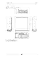
The C4-12 chassis is shipped in a plastic
bag that is placed inside a cardboard box.
When you unpack the chassis you must:
Make sure all items above are present.
Make sure the chassis has not been
damaged in any way.
STEP
2:
FRONT
HANDLE
INSTALLATION
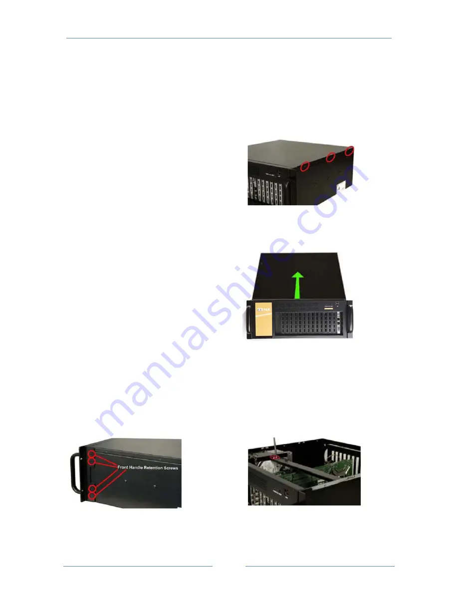
Two handles are shipped with the C4-12
chassis. The handles are installed on the
sides, at the front of the chassis. Each
handle is secured to the chassis by 4
retention screws. To install the handles,
please follow the steps below:
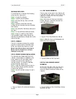
Step 1:
Align the retention screw holes on
the side of the chassis with the retention
screws in the handle.
Step 2:
Insert 4 retention screws for each
handle.
Figure 2 Insert 4 Front Handle Retention
Screws
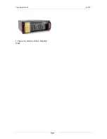
3.1:
TOP
COVER
REMOVAL
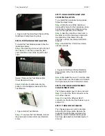
The top cover is secured to the chassis with
6 retention screws, three on each side of the
chassis. To remove the top cover, please
follow these steps:
Step a:
Remove all 6 top cover retention
screws. Remove 3 retention screws from
each side of the chassis.
Figure 3 Top Cover Retention Screws
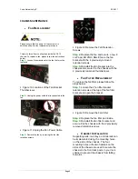
Step b:
Slide the top cover backwards and
Lift the top cover up gently.
Figure 4 Remove the Top Cover
STEP
3.2:
HOLD
‐
DOWN
CLAMP
REMOVAL
Detach the hold-down clamp by removing
the 2 screws located on one side of the
clamp and lift the hold-down clamp off the
chassis.
Figure 5 Remove the 2 Hold-Down Clamp
Retention Screws


