
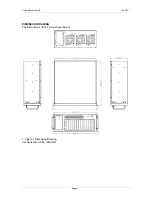
Xena Networks ApS
2009-11
Page
4
Figure 6 Lift the Hold-Down Clamp off the
Hold-Down Clamp Securing Hook
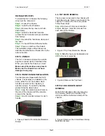
STEP
4:
TEST
MODULE
INSTALLATION
To install the Test Module please follow the
instructions below:
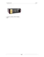
Step a:
Remove the slot cover at the front of
the chassis. To do this, remove the slot
cover retention screw at the top of the slot
cover.
Figure 7 Remove the Test Module Slot
Cover Retention Screw
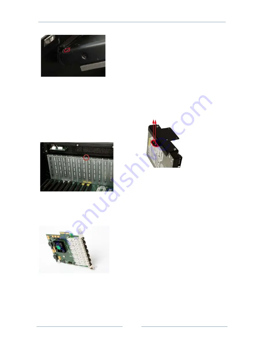
Step b:
Slide the Test Module into the
socket on the backplane reserved for the
Test Module.
Figure 8 Xena Test Module
Step c:
To secure the Test Module, reinsert
the previously removed slot cover retention
screw.
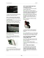
STEP
5:
HOLD
‐
DOWN
CLAMP
AND
COVER
INSTALLATION
To re-install the hold-down clamp, please
follow the steps below:
Step a:
Slide the end of the hold-down
clamp with 2 holes for the hold-down clamp
hooks into the hold-down clamp securing
hook on the right side of the chassis.
Step b:
Align the retention screw holes in
the other end of the hold-down clamp with
two retention screw holes in the clip
stretches out from the internal side HDD
bracket.
Step c:
Reinsert the 2 hold-down clamp
retention screws.
Figure 9 Hold-Down Clamp Retention
Screw Holes in the Clip of the Side HDD
bracket
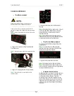
Step d:
Re-install the
cover. To do this, slide
the cover back over the chassis and reinsert
the 6 previously removed retention screws.
STEP
6:
PSU
CABLE
AND
ETHERNET
CABLE
CONNECTIONS
The following cables need to be connected.
Step 1:
Connect the PSU connector on the
rear of the chassis.
Step 2:
Connect the
Ethernet RJ-45
connector on the front of the chassis to your
LAN or PC.
STEP
7:
TURN
ON
THE
CHASSIS
The chassis power-on switch is located
behind the front logo plate. Remote the
magnetic front logo plate, and press the
power-on switch, re-attach the magnetic
front logo plate and boot will take approx 3
minutes.


