© Xena Networks – May 2022
3
QUICK OVERVIEW
Installing test modules in the ValkyrieBay chassis requires the following steps to be completed:
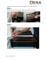
1. Remove the top lid by unscrewing the two finger screws at the back of the chassis.
2. Unscrew the restraining bar.
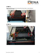
3. Remove the air flow cover by unscrewing the two finger screws on top and sliding it till it
releases.
4. Remove the alignment bar by loosening the two finger screws on top.
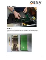
5. Choose which slot the module should sit in and remove the bracket.
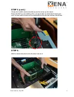
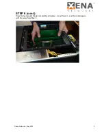
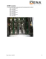
6. Slide the module into place and use the screw to secure it.
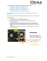
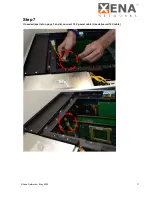
7. If needed (see list below), connect 12 V power cable.
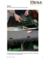
8. Mount the alignment bar by mounting the two finger screws.
9. Replace the air flow cover by sliding it till it in place and securing the two finger screws on top.
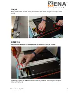
10. Position the restraining bar in place and screw the restraining bar tightly in place.
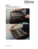
11. Replace top lid (Do not operate the chassis without top lid)
List of test modules not needing separate 12V supply:
-
Odin-1G-3S-6P
-
Odin-1G-3S-6P-E
-
Odin-1G-3S-2P-T
-
Odin-10G-1S-2P-T
List of modules needing separate 12V supply
:
-
Odin-1G-3S-6P-T1-RJ45
-
Odin-10G-1S-2P
-
Odin-10G-1S-6P
-
Odin-5G-4S-6P-CU
-
Odin-10G-3S-6P-CU
-
Odin-10G-5S-6P-CU
-
Odin-40G-2S-2P
-
Loki-100G-3S-1P
-
Loki-100G-5S-1P
-
Loki-100G-5S-2P
-
Odin-100G-3S-1P
-
Chi-40G-2S-2P
-
Chi-100G-5S-2P
(cont. on next page)
Please take precautions to avoid any ESD damage by using ESD wrist strap or other precaution.
Before opening the chassis, make sure to disconnect the power plugs.
Summary of Contents for ValkyrieBay Val-C12-2400G
Page 15: ...Xena Networks May 2022 15...

