background image

Version 1.0     January 2006

User’s  Manual

XENYX


1204/1204FX

Summary of Contents for 1204

Page 1: ...Version 1 0 January 2006 User s Manual XENYX 1204 1204FX...

Page 2: ...se of the polarized or grounding type plug A polarized plug has two blades with one wider than the other A grounding type plug has two blades and a third grounding prong The wide blade or the third pr...

Page 3: ...o channels 7 2 2 3 Aux sends stereo channels 7 2 2 4 Routing switch solo and channel fader 7 2 3 Connector panel and main section 7 2 3 1 Aux sends 1 and 2 7 2 3 2 Aux send connectors 1 and 2 7 2 3 3...

Page 4: ...nterface transfers the stereo mix from the console directly to a computer Both the recording signal and the playback signal from the computer can be monitored at the same time In this way you can use...

Page 5: ...devices such as radiators or power amps The console is connected to the mains via the supplied cable The console meets the required safety standards Blown fuses must only be replaced by fuses of the s...

Page 6: ...fader so that the effects volume in a channel corresponds to the position of the channel fader If this were not the case the effects signal of the channel would remain audible even when the fader is t...

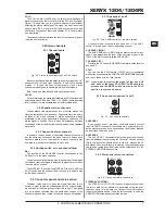
Page 7: ...the CLIP LED the SOLO switch and the channel fader function in the same way as the mono channels 2 3 Connector panel and main section Whereas it was useful to trace the signal flow from top to bottom...

Page 8: ...TURN 2 connectors which are routed to the main mix MAIN MIX ALT 3 4 The MAIN MIX ALT 3 4 switch routes the signal connected to STEREO AUX RETURN 2 to either main mix not pressed or submix Alt 3 4 pres...

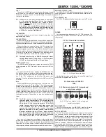
Page 9: ...nd the stereo line inputs The solo bus is as a rule switched post fader The PAN control in the channel strip offers a constant power characteristic This means that the signal is always at a constant l...

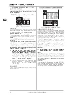
Page 10: ...phantom power supply SERIAL NUMBER Please note the important information on the serial number given in chapter 1 3 3 3 DIGITAL EFFECTS PROCESSOR Fig 3 1 Digital effects module only 1204FX 24 BIT MULT...

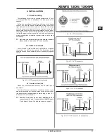
Page 11: ...screws holding the mixing console side panels to fasten the 19 rack mounts 4 2 Cable connections You will need a large number of cables for the various connections to and from the console The illustra...

Page 12: ...bal 10 kW unbal Max input level 22 dBu 5 SPECIFICATIONS Main outputs Type XLR electronically balanced Impedance approx 240 W bal 120 W unbal Max output level 28 dBu Control room outputs Type 1 4 TS co...

Page 13: ...nclosed list during normal business hours BEFORE returning the product All inquiries must be accompanied by a description of the problem BEHRINGER will then issue a return authorization number 2 Subse...

Reviews: