5
XENYX 1622FX/1832FX/2222FX/2442FX
s
Mix
:
All other mixing console functions fall under this vital category.
Creating a mix means primarily adjusting the volume levels
of individual instruments and voices to one another as well
as giving them the appropriate weight within the overall
frequency spectrum. Likewise, youll have to sensibly
spread individual voices across the stereo image of a signal.
At the end of this process, adjusting the level of the entire
mix to other equipment in the signal path is required (e. g.
recorder/crossover/amplifier).
The control surface of BEHRINGER mixing consoles is opti-
mized in such a way that these functions become easy to fulfil
while the signal path remains simple to follow.
1.2 The users manual
The users manual is designed to give you both an overview of
the controls, as well as detailed information on how to use them.
In order to help you understand the links between the controls,
we have arranged them in groups according to their function. If
you need to know more about specific issues, please visit our
website at http://www.behringer.com. Additional information and
explanations about various music industry/audio technology
terminology can be found on individual product pages as well as
in the glossary.
+
The block diagram supplied with the mixing console
gives you an overview of the connections between
the inputs and outputs, as well as the associated
switches and controls.
1.3 Before you get started
1.3.1 Shipment
Your mixing console was carefully packed in the factory to
guarantee safe transport. Nevertheless, we recommend that
you carefully examine the packaging and its contents for any
signs of physical damage, which may have occurred during
transit.
+
If the unit is damaged, please do NOT return it to us,
but notify your dealer and the shipping company
immediately, otherwise claims for damage or
replacement may not be granted.
1.3.2 Initial operation
Be sure that there is enough space around the unit for cooling
purposes and to avoid over-heating please do not place your
mixing console on high-temperature devices such as radiators
or power amps. The console is connected to the mains via the
supplied cable. The console meets the required safety standards.
Blown fuses must only be replaced by fuses of the same type
and rating.
+
Please note that all units must be properly
grounded. For your own safety, you should never
remove any ground connectors from electrical
devices or power cables, or render them in-
operative.
+
Please ensure that only qualified people install and
operate the mixing console. During installation and
operation, the user must have sufficient electrical
contact to earth, otherwise electrostatic discharges
might affect the operation of the unit.
1.3.3 Online registration
Please do remember to register your new BEHRINGER
equipment right after your purchase by visiting
www.behringer.com (alternatively www.behringer.de) and
kindly read the terms and conditions of our warranty carefully.
Should your BEHRINGER product malfunction, our goal is to
have it repaired as quickly as possible. To arrange for warranty
service, please contact the retailer from whom the equipment
was purchased. Should your BEHRINGER dealer not be located
in your vicinity, you may directly contact one of our subsidiaries.
Corresponding contact information is included in the original
equipment packaging (Global Contact Information/European
Contact Information). Should your country not be listed, please
contact the distributor nearest you. A list of distributors can be
found in the support area of our website (www.behringer.com).
Registering your purchase and equipment with us helps us
process your repair claims quicker and more efficiently.
Thank you for your cooperation!
2. CONTROL ELEMENTS AND
CONNECTORS
This chapter describes the various control elements of your
mixing console. All controls, switches and connectors will be
discussed in detail.
2.1 Mono channels
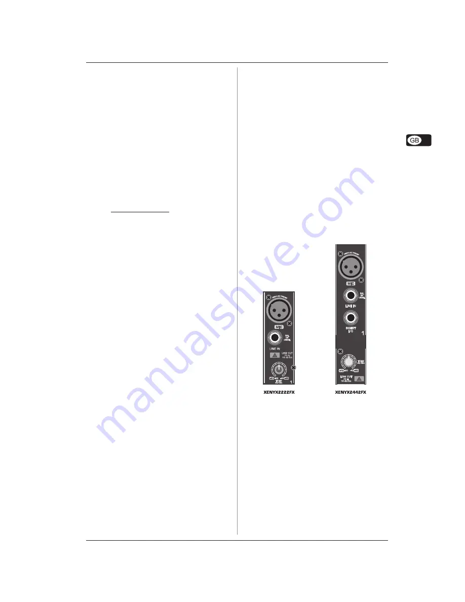
2.1.1 Microphone and line inputs
Fig. 2.1: Connectors and controls of mic/line inputs
MIC
Each mono input channel offers a balanced microphone input
via the XLR connector and also features switchable +48 V
phantom power supply for condenser microphones. The XENYX
preamps provide undistorted and noise-free gain as is typically
known only from costly outboard preamps.
+
Please mute your monitor system before you
switch on phantom power. Otherwise potentially
damaging thumps will be sent to your speakers.
Please also note the instructions in chapter 5.5
Voltage supply, phantom power and fuse.
LINE IN
Each mono input also has a balanced line input on a 1/4" jack.
You can also connect unbalanced devices using mono jacks to
these inputs.
+
Please remember that you can use either the
microphone input or the line input of a channel, but
not both at the same time!
2. CONTROL ELEMENTS AND CONNECTORS