Repairs and Adjustments
4-32
11/06
FaxCentre 2121/2121L
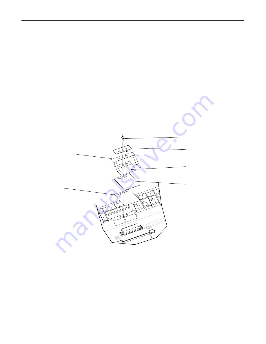
REP 16 Scanner Retard Pad
Parts list on PL 4
WARNING
Switch off the electricity to the machine. Disconnect the power cord from the customer supply
while performing tasks that do not need electricity. Electricity can cause death or injury. Moving
parts can cause injury.
Removal
1. Stand at the back of the machine.
2. Press the top cover release latch.
3. Press outwards on the latch and release the stop.
4. Hold the retard pad assembly while removing the mounting screw. Remove the assembly.
Note: The fixing plate is attached to a ground wire. Move the plate to one side to remove the
remaining parts.
Figure 1
Replacement
1. Visually inspect the new parts.
2. Put the new parts in place on the control panel in the following order: Slide plate, retard pad,
centre blade spring, side blade spring and fixing plate. Make sure the parts are oriented cor-
rectly. Insert the mounting screw and tighten it.
3. Press on the latch and close the control panel, letting the stop lock behind the latch.
Mounting screw
Fixing plate
Centre blade
spring
Retard pad
Side blade spring
Slide plate
Summary of Contents for 2121L - FaxCentre B/W Laser
Page 1: ...708P88662 11 06 Service Manual 708P88662 FaxCentre 2121 2121L ...
Page 20: ...Service Call Procedures 1 2 11 06 FaxCentre 2121 2121L Page intentionally blank ...
Page 28: ...Status Indicator RAPs 2 2 11 06 FaxCentre 2121 2121L Page intentionally blank ...
Page 44: ...Image Quality 3 2 11 06 FaxCentre 2121 2121L Page intentionally blank ...
Page 56: ...Repairs Adjustments 4 2 11 06 FaxCentre 2121 2121L Page intentionally blank ...
Page 108: ...Spare Parts List 5 4 11 06 FaxCentre 2121 2121L PL 2 Machine Assembly 1 3 5 6 2 4 ...
Page 110: ...Spare Parts List 5 6 11 06 FaxCentre 2121 2121L PL 3 Control Panel and Scanner 2 1 ...
Page 116: ...Spare Parts List 5 12 11 06 FaxCentre 2121 2121L PL 6 Control Panel Assembly 1 2 3 4 5 6 7 8 ...
Page 118: ...Spare Parts List 5 14 11 06 FaxCentre 2121 2121L PL 7 Paper Tray 1 2 ...
Page 122: ...Spare Parts List 5 18 11 06 FaxCentre 2121 2121L PL 9 Drive Transfer Unit ...
Page 124: ...Spare Parts List 5 20 11 06 FaxCentre 2121 2121L PL 10 Fuser Assembly 2 1 ...
Page 126: ...Spare Parts List 5 22 11 06 FaxCentre 2121 2121L PL 11 Power Supplies and ROS Unit ...
Page 128: ...Spare Parts List 5 24 11 06 FaxCentre 2121 2121L PL 12 Paper Feed Section ...
Page 130: ...Spare Parts List 5 26 11 06 FaxCentre 2121 2121L PL 13 Consumables Tools and Kits ...
Page 132: ...Spare Parts List 5 28 11 06 FaxCentre 2121 2121L Page intentionally blank ...
Page 134: ...General Procedures and Information 6 2 11 06 FaxCentre 2121 2121L Page intentionally blank ...
Page 187: ...General Procedures and Information FaxCentre 2121 2121L 11 06 6 55 Figure 1 ...
Page 206: ...General Procedures and Information 6 74 11 06 FaxCentre 2121 2121L GP 23 Service Log ...
Page 208: ...Wiring Diagrams 7 2 11 06 FaxCentre 2121 2121L Page intentionally blank ...
Page 219: ...Wiring Diagrams FaxCentre 2121 2121L 11 06 7 13 Main PBA and CPU PJ Locations Figure 1 ...
Page 220: ...Wiring Diagrams 7 14 11 06 FaxCentre 2121 2121L WD 1 Connection Diagram 1 of 5 Figure 1 ...
Page 221: ...Wiring Diagrams FaxCentre 2121 2121L 11 06 7 15 WD 2 Connection Diagram 2 of 5 Figure 1 ...
Page 222: ...Wiring Diagrams 7 16 11 06 FaxCentre 2121 2121L WD 3 Connection Diagram 3 of 5 Figure 1 ...
Page 223: ...Wiring Diagrams FaxCentre 2121 2121L 11 06 7 17 WD 4 Connection Diagram 4 of 5 Figure 1 ...
Page 224: ...Wiring Diagrams 7 18 11 06 FaxCentre 2121 2121L WD 5 Connection Diagram 5 of 5 Figure 1 ...


