October 2012
4-39
ColorQube 8570/8870 Service Manual
REP 2.12
Repairs and Adjustments
Xerox Internal Use Only - Revised, 3rd Revision
REP 2.12 Transfix Camshaft
Parts List on
PL 2.1 Item 12
Removal
CAUTION
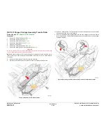
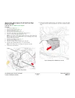
Use care when releasing the Transfix Module Spring Hooks. Move your lever handle towards
the center of the printer as indicated in
Figure 1
.
1.
Open the Front Door (
REP 1.1
).
2.
Remove the Control Panel Cover (
REP 1.5
).
3.
Remove the Control Panel (
REP 1.6
).
4.
Remove the Left Side Cover (
REP 1.10
).
5.
Remove the Right Side Cover (
REP 1.11
).
6.
Remove the Exit Cover (
REP 1.7
).
7.
Remove the Ink Loader (
REP 1.8
).
8.
Remove the Media Drive Assembly (
REP 4.5
).
9.
Remove the Exit Module (
REP 3.13
).
10. Remove the Outer Duplex Guide (
REP 3.4
).
11.
Remove the Upper Duplex Guide and Solenoid (
REP 3.5
).
12. Remove the Duplex Roller (
REP 3.8
).
13. Remove the I/O Board (
REP 5.10
).
14. Remove the Transfix Load Arms (
REP 2.21
).
15. Remove the Process Drive (
REP 4.13
).
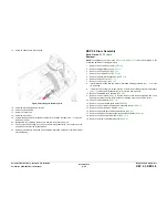
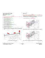
16. Slide the camshaft to the right, making sure the bearing slides over to the gear. Move the
camshaft down and slightly to the right, and then up to the left to remove it from the chas-
sis.
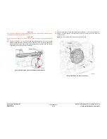
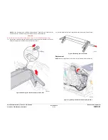
Figure 1 Removing the Transfix Camshaft
Replacement
CAUTION
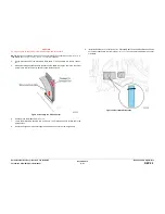
When replacing the I/O Board screws, torque to no more than 12 in.-lbs. Overtightening these
fasteners can result in irreversible damage to the chassis.
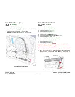
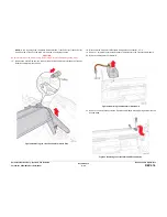
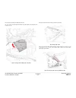
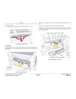
Position the corner of the I/O Board behind the Ground Plane before installing the
screws. Be sure to secure the Ground in front of the I/O Board.
CAUTION
Incorrectly mounting the I/O Board may short +3.3V power.
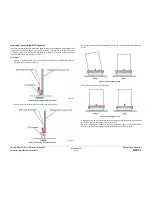
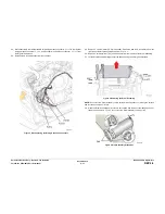
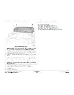
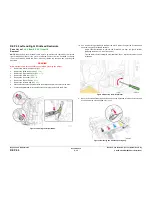
Figure 2 Installing the I/O Board - Correct Ground Plane position in front of the I/O Board
Figure 3 Installing the I/O Board - Incorrect Ground Plane position behind the I/O Board
Summary of Contents for COLORQUBE 8570
Page 1: ...ColorQube 8570 8870 Printer ColorQube 8570 8870 Service Manual Xerox Internal Use Only...
Page 2: ......
Page 423: ......

