October 2012
4-40
ColorQube 8570/8870 Service Manual
REP 2.13
Revised, 3rd Revision - Xerox Internal Use Only
Repairs and Adjustments
REP 2.13 Stripper Carriage Assembly/ Transfix Roller
Parts List on
PL 2.1 Item 13
,
PL 2.1 Item 14
Removal
1.
Remove the Control Panel Cover (
REP 1.5
).
2.
Remove the Control Panel (
REP 1.6
).
3.
Remove the Left Side Cover (
REP 1.10
).
4.
Remove the Right Side Cover (
REP 1.11
).
5.
Prop open the Exit Door.
6.
Remove the Outer Duplex Guide (
REP 3.4
).
7.
Remove the Upper Duplex Guide and Solenoid (
REP 3.5
).
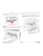
CAUTION
Be sure to unlock the ZIF connector to release the ribbon cable. Be careful when disconnecting
the one ribbon cable to prevent damaging the cable.
NOTE: The ribbon cable connector is the locking type connector and require unlocking prior to
ribbon cable removal and locking after reinstallation of the cable in order to make adequate
connection.
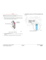
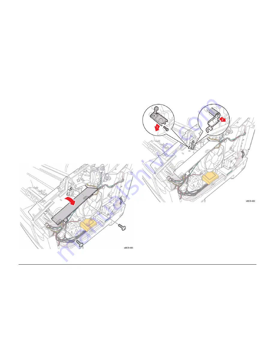
8.
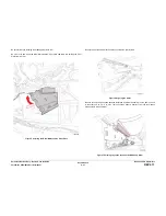
Remove 2 screws (plastic, T-20) that secure the I/O Board.
9.
Move the I/O Board away from the printer to access the I/O Board Ground screw.
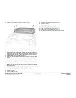
Figure 1 Removing the I/O Board Screws
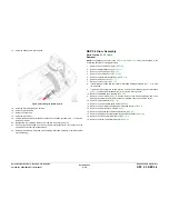
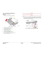
10. Remove 1 screw (plastic, T-20) that secures the I/O Board Ground and the Transfix Roller
Shaft Restraint, then remove the Restraint.
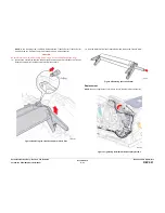
11.
Hold the Transfix Roller and Stripper Blade with one hand, engage the end of the Transfix
Roller Shaft with the Transfix Roller Shaft Restraint and pull the shaft out of the Stripper
Carriage Assembly.
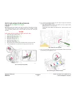
Figure 2 Removing the I/O Board Ground Screw and Transfer Roller Shaft
Summary of Contents for COLORQUBE 8570
Page 1: ...ColorQube 8570 8870 Printer ColorQube 8570 8870 Service Manual Xerox Internal Use Only...
Page 2: ......
Page 423: ......


