October 2012
4-41
ColorQube 8570/8870 Service Manual
REP 2.13
Repairs and Adjustments
Xerox Internal Use Only - Revised, 3rd Revision
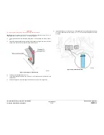
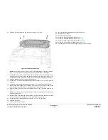
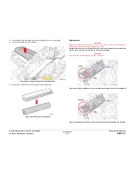
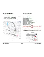
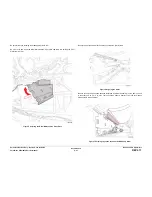
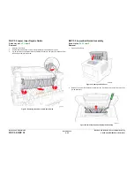
12. Lift the Stripper Carriage Assembly and Transfix Roller up and out of the chassis.
13. Remove the Stripper Carriage Assembly.
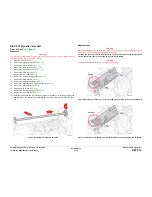
Figure 3 Removing the Transfix Roller Shaft Restraint
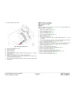
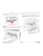
14. Remove the Transfix Roller from the Stripper Carriage Assembly.
Figure 4 Removing the Transfix Roller
Replacement
CAUTION
When replacing the I/O Board screws, torque to no more than 12 in.-lbs. Overtightening these
fasteners can result in irreversible damage to the chassis.
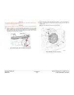
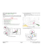
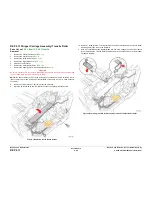
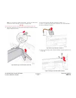
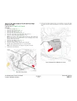
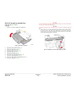
Position the corner of the I/O Board behind the Ground Plane before installing the
screws. Be sure to secure the Ground in front of the I/O Board.
CAUTION
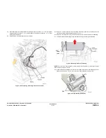
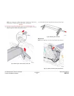
Incorrectly mounting the I/O Board may short +3.3V power.
Figure 5 Installing the I/O Board - Correct Ground Plane position in front of the I/O Board
Figure 6 Installing the I/O Board - Incorrect Ground Plane position behind the I/O Board
Summary of Contents for COLORQUBE 8570
Page 1: ...ColorQube 8570 8870 Printer ColorQube 8570 8870 Service Manual Xerox Internal Use Only...
Page 2: ......
Page 423: ......

