October 2012
4-44
ColorQube 8570/8870 Service Manual
REP 2.16
Revised, 3rd Revision - Xerox Internal Use Only
Repairs and Adjustments
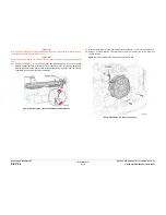
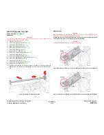
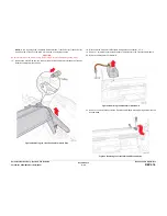
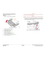
22. Remove 4 screws (metal, T-20), 2 at each end, that secure the Transfix Load Module to
the chassis.
Figure 5 Transfix Load Module Fasteners
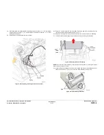
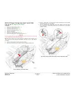
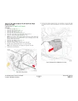
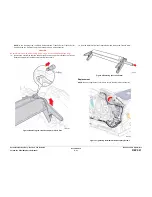
23. Loosen 1 screw that secures the Process Drive until the tip of the screw is even with the
inner side of the frame surface as shown in
Figure 6
.
Figure 6 Loosening the Process Drive Screw
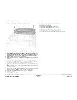
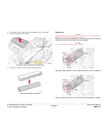
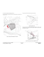
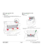
24. Rotate the top of the Transfix Load Module forward and spread the chassis slightly at the
right side to remove it.
NOTE: The Transfix Load Module fits tightly in the chassis. Some force is needed to
remove it.
Figure 7 Removing the Transfix Load Module
Replacement
Place a small amount of Rheolube 768 grease (P/N 070E00890) in the groove at the end of
each Transfix Load Arm before reattaching the Spring Hooks. Also, when replacing the
Grounding Springs on the Transfix Load Module, make sure the springs rest below the Transfix
Camshaft.
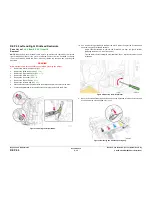
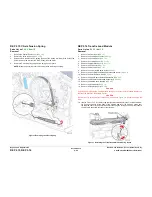
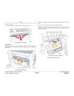
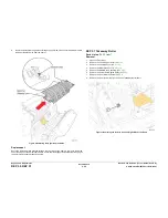
Be sure to tighten 1 screw to secure the Process Drive.
Figure 8 Tightening the Process Drive Screw
After replacing the Exit Module, perform the Wiper Blade Alignment procedure (
ADJ 1.1
). Fault
codes 91,720 ~ 91,723 indicate misalignment of the Wiper Assembly.
Summary of Contents for COLORQUBE 8570
Page 1: ...ColorQube 8570 8870 Printer ColorQube 8570 8870 Service Manual Xerox Internal Use Only...
Page 2: ......
Page 423: ......

