October 2012
4-75
ColorQube 8570/8870 Service Manual
REP 4.7, REP 4.8
Repairs and Adjustments
Xerox Internal Use Only - Revised, 3rd Revision
REP 4.7 Electronics Module Fan
Parts List on
PL 4.1 Item 7
Removal
1.
Remove the Control Panel Cover (
REP 1.5
).
2.
Remove the Left Side Cover (
REP 1.10
).
3.
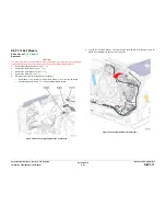
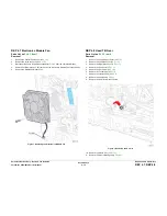
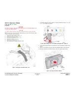
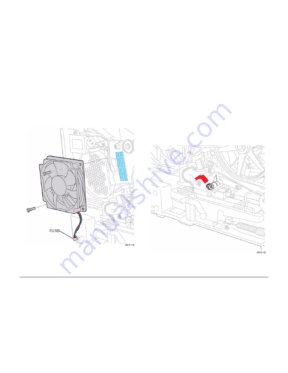
Disconnect the Fan wiring harness connector
P/J105
from the Left Side Harness.
4.
Remove 2 screws (plastic, T-20) that secure the Electronics Module Fan to the chassis.
5.
Remove the Electronics Module Fan.
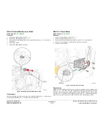
Figure 1 Removing the Electronics Module Fan
REP 4.8 Head Tilt Gear
Parts List on
PL 4.1 Item 8
Removal
1.
Remove the Control Panel Cover (
REP 1.5
).
2.
Remove the Left Side Cover (
REP 1.10
).
3.
Remove the Right Side Cover (
REP 1.11
).
4.
Remove the Exit Cover (
REP 1.7
).
5.
Remove the Ink Loader (
REP 1.8
).
6.
Remove the Funnel Cap (
REP 2.1
).
7.
Remove the Jetstack Cap (
REP 2.2
).
8.
Remove the Printhead (
REP 2.3
).
9.
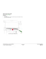
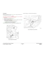
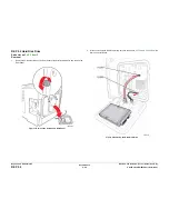
Remove the KL-Clip from the left side.
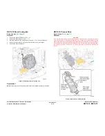
Figure 1 Removing the KL-Clip
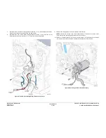
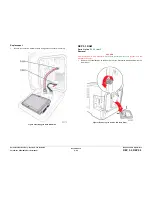
10. Remove the Waste Tray (
REP 1.15
).
11.
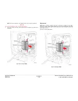
Remove the X-Axis Bias Spring (
REP 2.24
).
Summary of Contents for COLORQUBE 8570
Page 1: ...ColorQube 8570 8870 Printer ColorQube 8570 8870 Service Manual Xerox Internal Use Only...
Page 2: ......
Page 423: ......


