October 2012
4-77
ColorQube 8570/8870 Service Manual
REP 4.8, REP 4.9
Repairs and Adjustments
Xerox Internal Use Only - Revised, 3rd Revision
Replacement
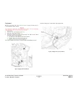
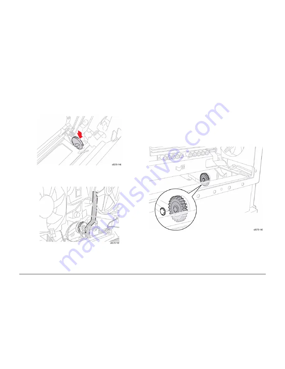
The leaf spring on the back side of the chassis must be behind the gear to engage. Lubricate
the curved surface of the gear using a small amount of Rheolube 768 grease (P/N
070E00890).
1.
Remove the Leaf Spring from the chassis.
2.
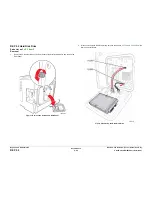
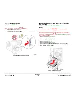
Partially insert the Head Tilt Gear Shaft into the chassis.
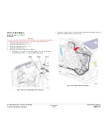
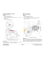
Figure 6 Replacing the Head Tilt Gear
3.
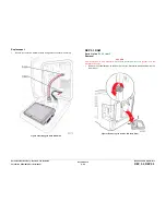
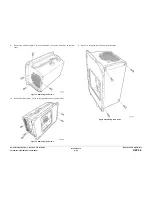
Replace the spring. Turn the Head Tilt Gear while inserting the spring to guide the spring
to its proper position behind the gear.
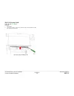
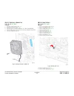
Figure 7 Head Tilt Spring Alignment
4.
Seat the gear by lifting the Head Tilt Solenoid Actuator.
5.
Replace the KL-Clip on the end of the Head Tilt Gear Shaft.
6.
Perform the Homing the Printhead Forward to Print Position procedure (
ADJ 1.2
) and
Process Drive Alignment procedure (
ADJ 1.3
) before restoring the printer power.
REP 4.9 Tray 2 Lift Motor Gear
Parts List on
PL 4.1 Item 9
Removal
1.
Remove Tray 2.
2.
Remove the Control Panel Cover (
REP 1.5
).
3.
Remove the Left Side Cover (
REP 1.10
).
4.
Remove the Right Side Cover (
REP 1.11
).
5.
Remove the Exit Cover (
REP 1.7
).
6.
Remove the Ink Loader (
REP 1.8
).
7.
Remove the Electronics Module (
REP 5.1
).
8.
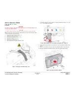
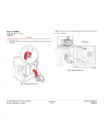
Remove the Tray 2 Lift Motor Gear by prying the Push Nut off the shaft.
NOTE: Replace the Push Nut with a new one when installing the gear.
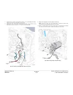
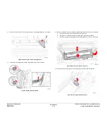
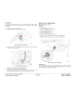
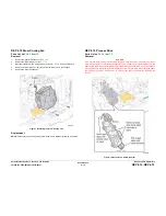
Figure 1 Removing the Lift Motor Gear
Replacement
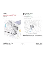
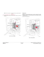
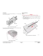
Check that the bushing tabs are properly seated in the chassis. To seat the new Push Nut,
position the Push Nut so the fingers point away from the shaft. Place a 3/8 in. nut driver over
the nut and press firmly to seat the nut on the shaft.
Summary of Contents for COLORQUBE 8570
Page 1: ...ColorQube 8570 8870 Printer ColorQube 8570 8870 Service Manual Xerox Internal Use Only...
Page 2: ......
Page 423: ......

