October 2012
4-91
ColorQube 8570/8870 Service Manual
REP 5.6
Repairs and Adjustments
Xerox Internal Use Only - Revised, 3rd Revision
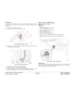
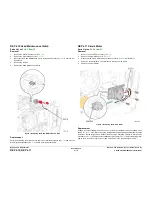
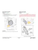
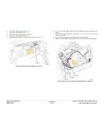
Replacement
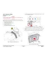
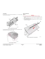
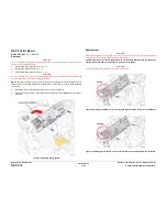
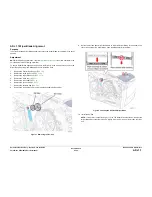
Be sure to connect
P/J703
on the Main Controller Board and
JDC1
on the Power Supply
Board to the Power Control Board.
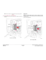
Figure 7 Connector and Screw Locations
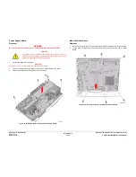
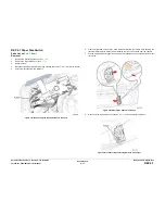
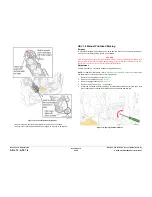
Be sure to seat the two side corners of the Panel on top of the Power Control Board, and the
middle section of the Panel on the outside of the Cage.
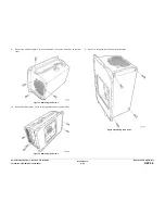
Figure 8 Installing the Side Panel
Power Control Board
Removal
WARNING
Be sure to disconnect AC power prior to disassemble the Electronics Module.
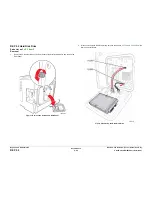
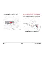
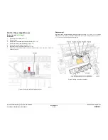
1.
Turn the Board Assembly Module over with the bottom of the Power Control Board facing
upward.
2.
Remove 3 screws (metal, T-9) that secure the Power Control Board and remove the
Power Control Board support rail.
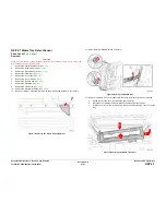
3.
Gently wiggle the Power Control Board to disconnect the
P/J403
and
P/J601
connectors
from the Power Supply Board.
Figure 9 Removing the Screws and Support Rail
Summary of Contents for COLORQUBE 8570
Page 1: ...ColorQube 8570 8870 Printer ColorQube 8570 8870 Service Manual Xerox Internal Use Only...
Page 2: ......
Page 423: ......

