October 2012
6-32
ColorQube 8570/8870 Service Manual
Electrical Troubleshooting
Revised, 3rd Revision - Xerox Internal Use Only
General Troubleshooting
Checking F501 Fuse
1.
Pull the power plug to turn Off the machine.
2.
Open the Electronics Module Rear Cover.
3.
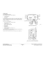
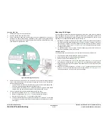
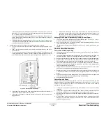
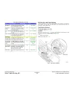
With an ohmmeter, measure the surface-mount Fuse F501 (labeled F501). The Fuse is
located on the Power Control Board, immediately to the right of the large Main Board
interconnect connector (which is just underneath the Main Board’s RAM DIMMs). A bad
Fuse will measure greater than 1 ohm.
Figure 9 Measuring the F501 Fuse
4.
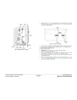
Check for a short on the 3.3V bus or the 3.3V SLEEP bus. Locate the voltage test points
on the Power Control Board, near the rear cover opening. They are just to the right of a
pair of electrolytic capacitors.
•
Look for TP820 3.3V. Measure that point to the ground. Good should measure 500 -
600 ohms; bad measurement should be less than 2 ohms.
•
Look for TP822 3.3V SLEEP (
Figure 2
). Measure that point to ground. Good should
measure 250 - 450 ohms; bad measurement should be less than 2 ohms.
5.
If a short is present, then you must systematically look for the short.
a.
Remove the Left Side Cover (
REP 1.10
) and re-measure the test point.
b.
Remove the Right Side Cover (
REP 1.11
) and re-measure the test point.
c.
Remove the Ink Loader (
REP 1.8
) and check the test point.
d.
Look for pinched wires and bent pins on the I/O Board. 3.3 volts and 3.3 volts sleep
are carried on the printer’s gray ribbon cables. Disconnect the harnesses to isolate,
if necessary.
Measuring AC Voltages
AC line voltages are present on the Power Supply and in the printer, via the heaters, while the
printer is plugged into an AC outlet. The power switch position is detected by software and
proper shut down is followed by a power off signal to the Power Supply. The printer may be
operating for a considerable time after the switch is turned off.
1.
AC Input: With a DMM set to measure AC voltages, measure the power being supplied to
the printer; it should measure between 90 to 134 VAC (115 VAC nominal) or 180 to 254
VAC (220 VAC nominal). The service diagnostic function may also be used to measure
the input voltage. Refer to the
Service Diagnostics Tests
in Chapter 6 (General Trouble-
shooting) for more details.
2.
If a heater shorts fuse, F2 or F3 opens. The Power Supply may not shut down; however, a
fault code is displayed on the Control Panel.
Testing F2 and F3
The Printhead and Ink Loader connect to F2. The Drum and Preheater connect to F3.
1.
Turn the power switch off and wait for the printer to shut down.
2.
Disconnect the power cord from the Electronics Module.
3.
Remove the Ink Loader Assembly (
REP 1.8
).
4.
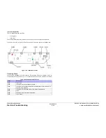
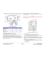
From the back of the printer, there is one heater cable connector (
P/JAC3
) on the left
above the power switch and two (
P/JAC2
and
P/JAC1
) connectors under the Ink Loader.
5.
Place the Power Switch in the On position. If the power switch is in the Off position, false
readings may result.
6.
Measure the resistance between
P/JAC3
Pins 3, 4, or 5 (toward the bottom rear of the
printer on
P/JAC3
), and the lowest pin on the AC input connector (
AC Inlet
) (
Figure 10
).
If the meter measures 0 ohms, F3 has not been damaged.
Summary of Contents for COLORQUBE 8570
Page 1: ...ColorQube 8570 8870 Printer ColorQube 8570 8870 Service Manual Xerox Internal Use Only...
Page 2: ......
Page 423: ......


