October 2012
6-33
ColorQube 8570/8870 Service Manual
Electrical Troubleshooting
General Troubleshooting
Xerox Internal Use Only - Revised, 3rd Revision
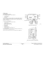
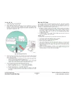
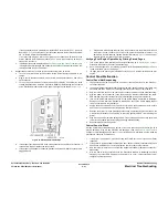
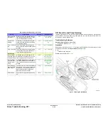
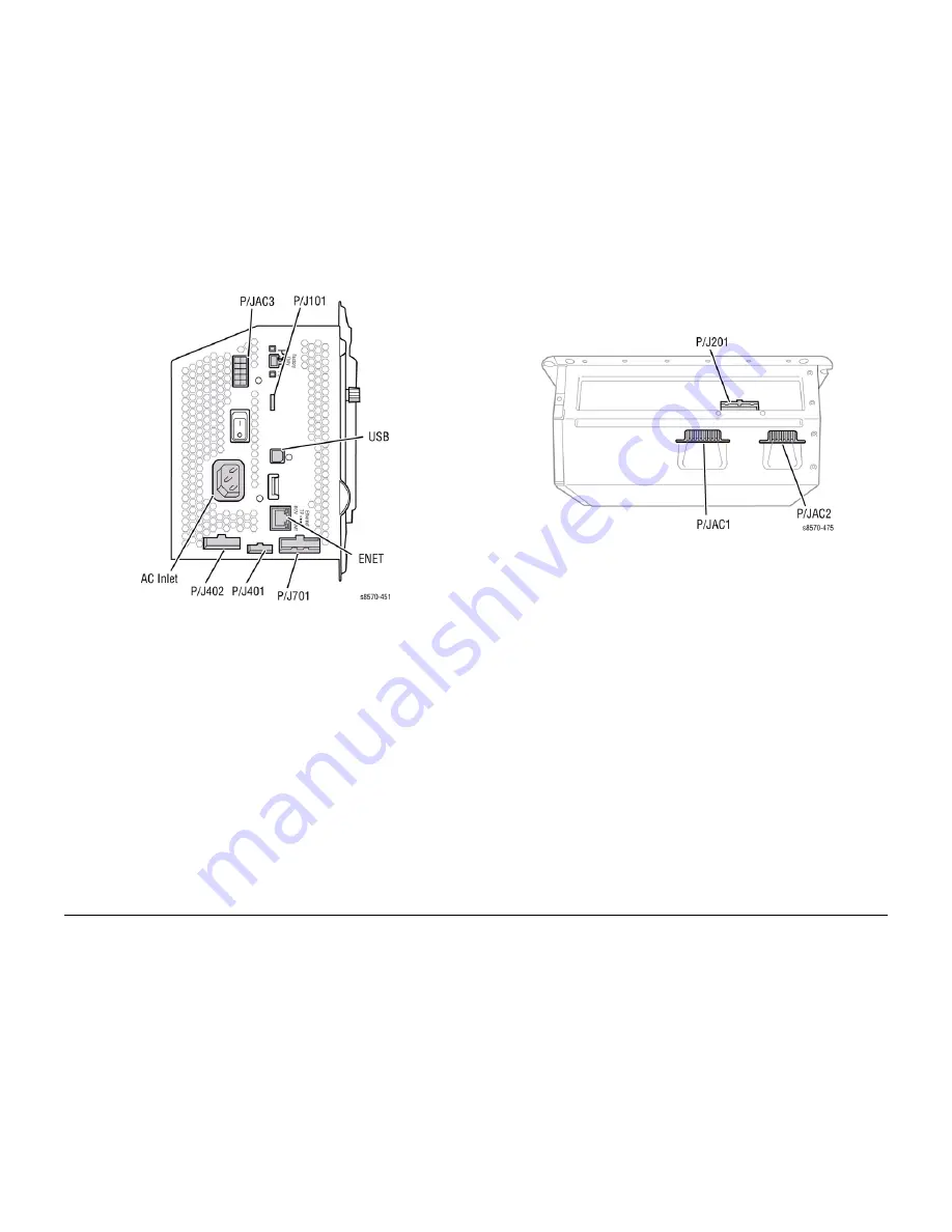
Figure 10 Wiring Harness Connectors
7.
Measure between
P/JAC1
Pin 9 (the pin closest to the power inlet) under the Ink Loader
and (again) the lowest pin on the AC input connector (
AC Inlet
). If the meter measures 0
ohms, F2 has not been damaged.
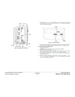
Figure 11 Connector Locations
8.
The fuses are not serviceable. Check the affected heaters for short circuits across the
heater and to ground. Replace the Electronics Module (
REP 5.1
) to replace the fuses.
Checking for Shorted and Leaky Triacs
1.
Turn the power switch off.
2.
IMPORTANT: Disconnect the power cord from the Electronics Module.
3.
Remove the Ink Loader Assembly (
REP 1.8
).
4.
From the back of the printer, there is one heater cable connector (
P/JAC3
) on the left
above the power switch and two (
P/JAC2
and
P/JAC1
) under the Ink Loader.
5.
Place the Power Switch in the On position. If the power switch is left in the Off position,
false readings may result.
6.
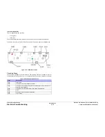
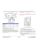
Measure the resistance between the highest pin on the AC Input Connector (
AC Inlet
)
(
Figure 12
) and the triac channels (listed in
Table 3
). If the meter reads greater than 50k
ohms, the triac has not been damaged.
Summary of Contents for COLORQUBE 8570
Page 1: ...ColorQube 8570 8870 Printer ColorQube 8570 8870 Service Manual Xerox Internal Use Only...
Page 2: ......
Page 423: ......


