October 2012
6-40
ColorQube 8570/8870 Service Manual
Electrical Troubleshooting
Revised, 3rd Revision - Xerox Internal Use Only
General Troubleshooting
Maintenance Kit Missing
1.
Drum Maintenance Unit missing or not fully seated.
a.
Fully install Drum Maintenance Unit.
2.
Connector not fully seated.
a.
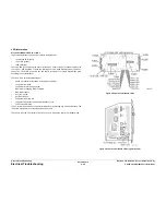
Check I/O Board connector
P/J901
for proper mating.
3.
Replace the Drum Maintenance Unit (
REP 1.16
). If that does not fix the problem, then
replace the Drum Maintenance Pivot Plate (
REP 2.17
).
Waste Tray Missing
1.
Waste Tray missing or not fully seated.
a.
Fully install the Waste Tray.
2.
Connector not fully seated.
a.
Check the I/O Board connector
P/J102
for proper mating.
3.
Check that the Waste Tray Sensor is correctly installed at the end of the Waste Tray
Cover.
Optional Features Not Available
1.
Printer configuration incorrect.
a.
Verify proper configuration of printer using the Control Panel.
2.
Computer print driver configured incorrectly.
a.
Examine print driver setup to ensure printer driver setup does not override desired
features set via the Control Panel.
b.
Verify that the driver correctly indicates the options installed on the printer. Correct
the driver if necessary. When options are added to the printer, such as a Lower Tray
Assembly, the print driver may need to be updated.
3.
Configuration Card failure.
a.
Verify the Configuration Card is properly oriented and fully inserted.
b.
Verify printer model purchased corresponds to features expected.
c.
Clean the Configuration Card contacts with isopropyl alcohol, reinstall, and retest.
d.
Swap the Configuration Card with a known working card. If the printer works, replace
the card with one containing identical features as originally purchase.
e.
The Configuration Card enables certain optional features in the printer. Care must be
taken to duplicate the features of the original printer when replacing the card.
525-Sheet Feeder Does Not Function
1.
Thermal safety fuse blown.
a.
Power cycle the printer.
b.
The safety fuse is a self resetting device. Power cycling ensures the fuse cools
enough to reset itself.
2.
525-Sheet Feeder faulty.
a.
Turn off the printer and wait 30 seconds for power supply capacitors to discharge.
b.
Replace 525-Sheet Feeder (
REP 3.12
).
c.
Perform full test of the printer.
Printer Does Not Print, LEDs are On and the Display is Frozen with No
Errors
1.
Non-specific electronics failure.
a.
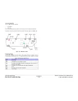
Double check PS and PE indicators for any fault code information. The printer self
test is usually able to detect a failure that would cause this symptom. Check for the
fault code may save debugging time.
b.
If the PS and PE indicators are steady and dimly-on, replace the Electronics Module
(
REP 5.1
) and retest printer.
c.
If the PS and PE indicators are blinking, brightly-on, or totally off, continue debug-
ging. A dim but steady on condition indicates some firmware was not properly
loaded into a logic circuit.
d.
With the power cord connected, touch the metal Electronics Module to discharge
any static electricity.
e.
Turn off printer and wait 30 seconds for the Power Supply capacitors to discharge.
f.
Unplug the power cord and remove the printer's covers.
g.
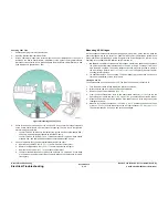
Unplug the following Electronics Module connectors:
•
Power Control to I/O Board (
P/J701
)
•
Power Control Right (
P/J402
)
•
Printhead Data (
P/J201
)
•
Wave Amp Signal (
P/J901
)
•
Power Control Left (
P/J302
)
•
Y-Axis Motor (
P/J301
)
This step removes all other circuits so the Electronics Module can be tested alone.
h.
Plug in the power cord and turn on the printer.
i.
The PE and PS indicators should flash a fault code reporting that the Control Panel
is missing. If the proper fault message is not flashed, replace the Electronics Module
(
REP 5.1
) and retest the printer. If PE and PS indicators flash, continue with debug.
j.
Turn off the printer and wait 30 seconds for the Power Supply capacitors to dis-
charge.
k.
Unplug the following Electronics Module connectors:
•
Power Control to I/O Board (
P/J701
)
•
Power Control Right (
P/J402
)
•
Printhead Data (
P/J201
)
•
Wave Amp Signal (
P/J901
)
•
Power Control Left (
P/J302
)
•
Y-Axis Motor (
P/J301
)
This step prevents any faults from the Motors, Clutches and Sensors from prevent-
ing the I/O Board and Control Panel from functioning.
l.
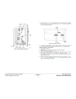
Plug in the I/O Board connector (
P/J701
) to the Electronics Module. This step adds
the I/O Board and Control Panel to the Electronics Module.
m.
Turn on the printer.
n.
If the Electronics Module, I/O Board and Control Panel are working, fault code
91,900 should appear on the display to indicate the Printhead is disconnected. If the
correct fault code is displayed, continue with the next steps of the procedure.
Summary of Contents for COLORQUBE 8570
Page 1: ...ColorQube 8570 8870 Printer ColorQube 8570 8870 Service Manual Xerox Internal Use Only...
Page 2: ......
Page 423: ......


