October 2012
8-4
ColorQube 8570/8870 Service Manual
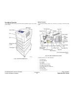
Operational Overview
Revised, 3rd Revision - Xerox Internal Use Only
Theory of Operation
Process Drive
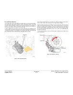
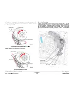
The Process Drive is an open loop system that transmits torque to two main Camshaft assem-
blies, One Camshaft assembly controls the Transfix Roller loading, and the other controls the
Drum Maintenance System and Printhead Tilt System.
Media Drive
The Media Drive Assembly controls each Roller in the media transport system. The Media
Drive Assembly includes a Drive Motor, Gearbox, Solenoid, and two Clutches. The Media
Drive Motor also drives the Wiper Assembly through a gear train and Clutch on the Exit Mod-
ule.
Ink Loader
The Ink Loader melts the ink as required by the Printhead. The melted ink drops into the Ink
Reservoirs of the Printhead underneath the Ink Loader.
Printhead
The Printhead interfaces with the electronics of the printer to jet ink onto the Drum surface to
create an image. The Printhead includes 1236 interleaved jets (309 of each primary color) to
provide the ability to electronically turn Off a weak or missing jet to restore image quality.
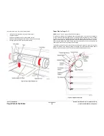
Drum Maintenance System
The Drum Maintenance System creates a thin intermediate liquid surface, a layer of silicone
oil, on the surface of the Drum prior to printing. The oil keeps the ink from sticking to the Drum’s
surface and facilitates its transfer to the sheet of paper or transparency film.
Preheat and Deskew
The Preheat and Deskew serves to ensure that the print media (paper, envelope, or transpar-
ency film) aligns properly to the Drum and that the media is sufficiently warms to facilitate
transfer of the image from the Drum to the media.
Drum and Transfix System
The image is first printed as a “mirror” image on the rotating Drum. A sheet of warmed media
feeds from the Preheater and passes between the Drum and the Transfix Roller. The process
gear train then loads the Transfix System and presses the paper to the Drum to adhere the
image.
Exit Module
The Exit Module is controlled by the Electronics Module. Media is output directly to the Output
Tray on the Ink Loader.
Purge System
The Purge System uses an air hose and Purge Pump to pressurize the Printhead to purge
debris or air bubbles that may be obstructing the Printhead jets.
Electronics Module
The Electronics Module includes the Main Controller Board, Power Control Board, and the
Power Supply.
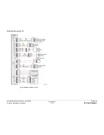
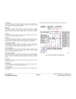
The following diagram illustrates the Electronic Module’s device controller function.
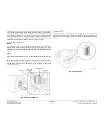
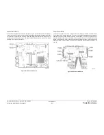
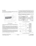
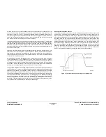
Figure 3 ColorQube 8570/8870 Component Diagram
Summary of Contents for COLORQUBE 8570
Page 1: ...ColorQube 8570 8870 Printer ColorQube 8570 8870 Service Manual Xerox Internal Use Only...
Page 2: ......
Page 423: ......

