October 2012
8-12
ColorQube 8570/8870 Service Manual
Printer Electronics
Revised, 3rd Revision - Xerox Internal Use Only
Theory of Operation
Power Supply
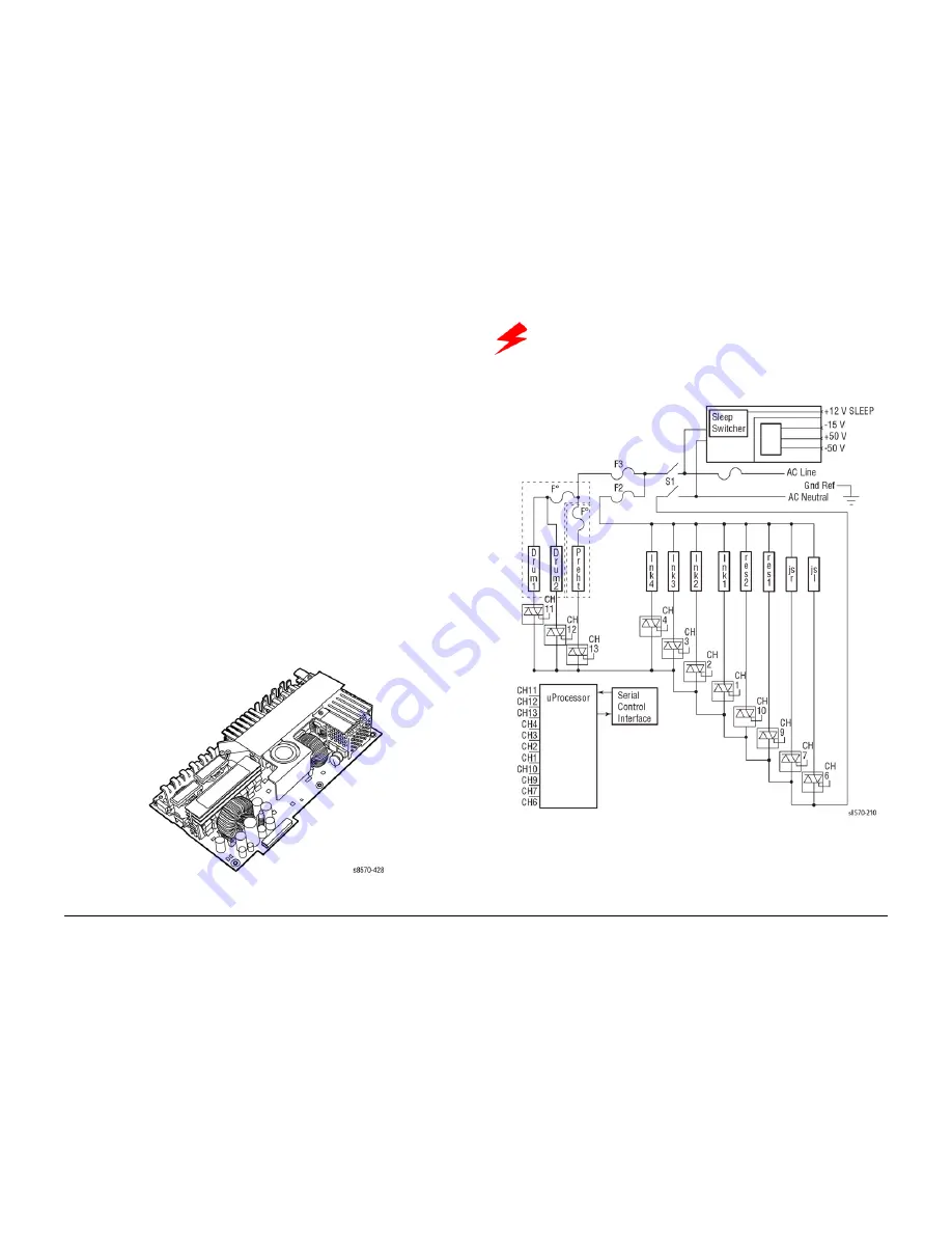
There are no field adjustments on the Power Supply. In general, the Power Supply has two
main, yet interrelated sections: the AC section and the DC section. In the AC section, power is
routed to 11 triacs. Under the Main Board Logic Control, the triacs supply AC power to the 11
heaters in the system.
Two fuses provide current protection to the triacs. Fuses F2 and F3 protect the power supply
from, most often, a shorted triac caused by a defective heater. If the F2 or F3 fuses blow, the
Electronics Module (and, of course, the defective heater must be replaced). Otherwise uncon-
trolled, with the heater replaced but the triac shorted, AC power may be applied to the heater.
Each time the Main Controller Board turns on a triac to activate a heater, it is turned on for only
a fraction of a second. The Main Controller Board must constantly readdress each heater it
wants to remain on. This means if the print engine firmware should fail, the heaters automati-
cally shut off.
The printer is also protected by thermal fuses. A thermal fuse opens in the unlikely event of a
“runaway” heater following a hardware failure. The Drum Fuse is located in the Drum and the
Preheater thermal fuses are located on the Preheater. Additional thermal fuses are located on
the Printhead, on the chassis outside the Printhead and on the ink melting elements. An open
thermal fuse is a likely indication of a leaky or shorted triac in the power supply. It is best to ver-
ify that the triacs are functional when replacing a heater with an open thermal fuse.
The DC Power Supply gen 12V_SLEEP, -15V, and +/- 50V. These voltages are used
directly or regulated to other voltage values as needed by various circuits in the printer. The
Power Control Board reg50V to +12V and 3.3V to a local 1.8V. The Main Controller
Board also has regulators pro3.3V, +2.5V, +1.8V, +1.2V, and +1.0V. The HDD Option
Board has a regulator conv12V_SLEEP to +5V for use by the HDD. The Power Supply
outputs just +12V_SLEEP in Power Saver modes. Fuse F1 provides protection for the switch-
ing Power Supply in the DC section.
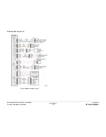
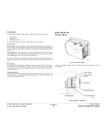
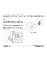
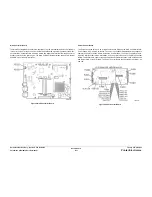
Figure 7 Power Supply
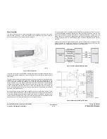
Wiring Diagram
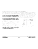
Figure 8 Power Supply Wiring Diagram
WARNING
Do not touch the Power Supply; AC voltages and DC voltages up to 400V are
present. The power switch does not disconnect power from the printer. The
power switch signals the supply and the printer logic to begin a shutdown
sequence.
Summary of Contents for COLORQUBE 8570
Page 1: ...ColorQube 8570 8870 Printer ColorQube 8570 8870 Service Manual Xerox Internal Use Only...
Page 2: ......
Page 423: ......


