October 2012
8-13
ColorQube 8570/8870 Service Manual
Printer Electronics
Theory of Operation
Xerox Internal Use Only - Revised, 3rd Revision
FPGA
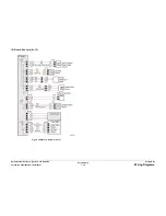
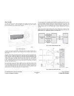
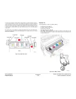
The FPGA is the Printhead interface and motor controller for the ColorQube 8570/8870 printer.
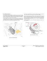
Figure 9
illustrates the Block Diagram for FPGA.
Figure 9 FPGA Block Diagram
Motors
Y-Axis Motor
The Y-Axis Motor is a DC Motor with an encoder that is used to turn the Drum. The Power Con-
trol Board drives the Y-Axis Motor with an H-bridge transistor configuration. An H-bridge config-
uration is used so the Motor can turn in both directions.
Process Motor
The Process motor is a DC Motor with an encoder that is used to turn the Drum. The Power
Control Board drives the Process Motor with an H-bridge transistor configuration. An H-bridge
configuration is used so the Motor can turn in both directions.
Media Path Motor
The Media Path Motor is a DC Motor with an encoder that is used to turn the paper feed mech-
anism. The Media Path Motor also move the head wipe when the Head Maintenance Clutch is
engaged. The Power Control Board drives the Media Path Motor with an H-bridge transistor
configuration. An H-bridge configuration is used so the Motor can turn in both directions.
X-Axis Motor
The X-Axis Motor is a current controlled stepper motor. The Power Control Board drives the X-
Axis Motor with two H-bridge transistor configurations one for each phase.
Elevator Motor
The Elevator Motor is a DC motor used to raise the paper to the pick. The Power Control Board
drives the Elevator Motor with the +12V coming from the power supply. The Elevator Motor is
current limited to 112mA. It has a brake that shorts both motor leads. This prevents the motor
from coasting and brings the motor to a more precise stop. The Elevator motor and the Brake
have a lock out in the PLD to prevent both from being activated at the same time, which would
cause a shoot through condition that would damage the drivers.
Fans
Electronics Fan
The Power Control Board drives the Electronics Fan by providing 12V, ground and sending a
3.3V pulse to the Fan to turn the Fan on. This allows the Fan to be pulse width modulated to
reduce the speed of the Fan, by reducing the effective voltage.
Drum Fan
The Power Control Board drives the Drum Fan by providing 12V to one side of the Fan and
switching the ground on the other side. This allows the Fan to be pulse width modulated to
reduce the speed of the Fan, by reducing the effective voltage.
Summary of Contents for COLORQUBE 8570
Page 1: ...ColorQube 8570 8870 Printer ColorQube 8570 8870 Service Manual Xerox Internal Use Only...
Page 2: ......
Page 423: ......

