October 2012
8-29
ColorQube 8570/8870 Service Manual
Print Process
Theory of Operation
Xerox Internal Use Only - Revised, 3rd Revision
Drum Maintenance System
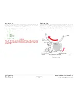
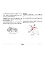
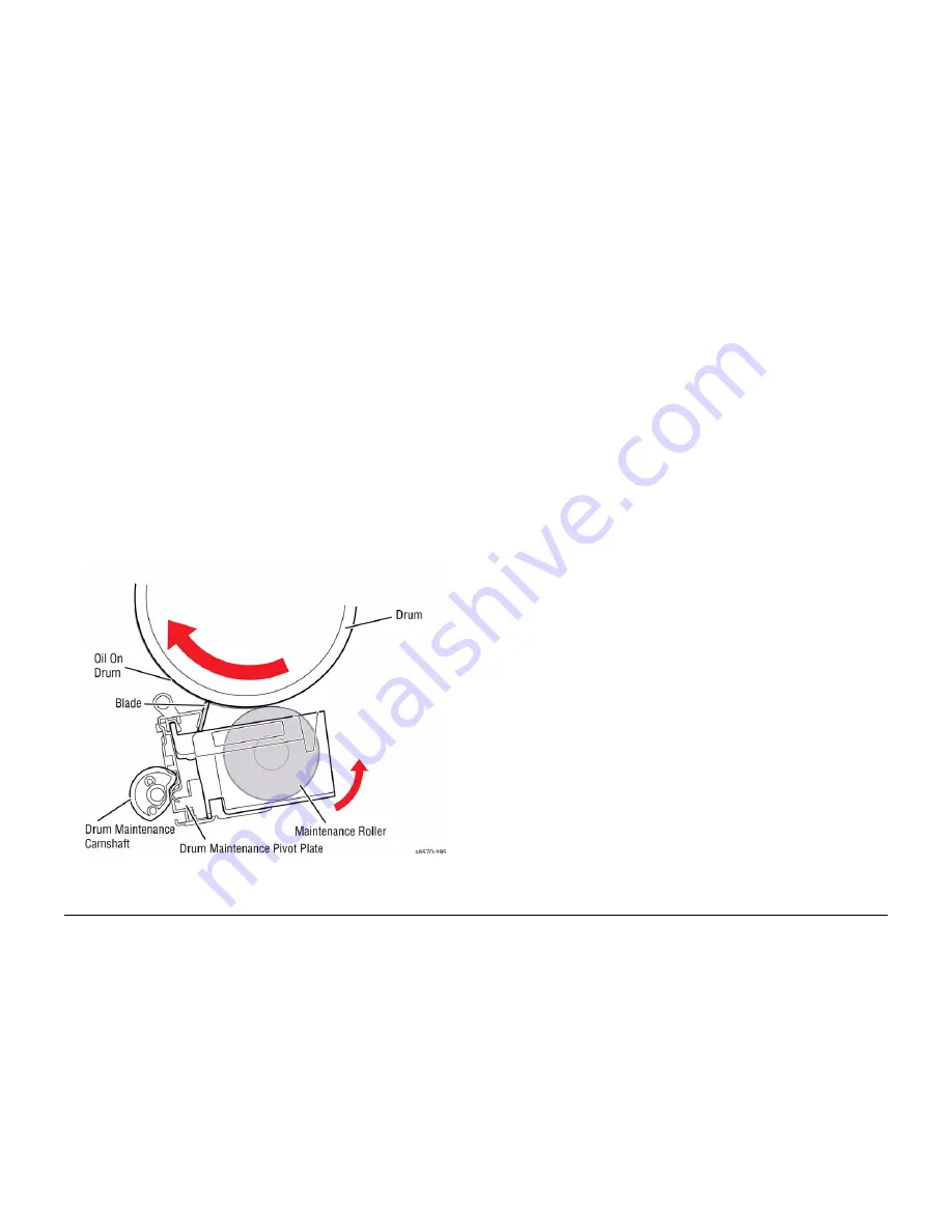
The Drum Maintenance System creates a thin layer of silicone oil on the surface of the Drum
prior to printing. The oil keeps the ink from sticking to the Drum’s surface and facilitates image
transfer to the media. The oil is contained in a porous foam Roller in the Drum Maintenance
Unit.
Prior to each print, the Process Drive rotates the Drum Maintenance Camshaft to move the
Drum Maintenance Pivot Plate, forcing the oil Roller and Wiper Blade against the Drum. The
Wiper Blade produces a smooth and even oil film across the Drum’s surface. The excess oil
drains back into the Drum Maintenance Unit through a felt filter for reuse. As the Drum com-
pletes one rotation, the Process Drive rotates the Cam lowering the oil Roller and Wiper Blade
away from the Drum.
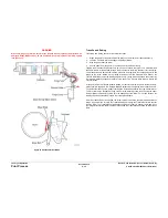
The Drum has a floating deadband area. The deadband is a narrow section of the Drum’s sur-
face containing excess oil and other debris cleared by the Drum Maintenance Wiper Blade. An
oil bar is left on the Drum surface in this deadband area as the Blade is lowered from the Drum.
The deadband area’s location is controlled to keep it outside of the Drum’s image area.
An EEPROM, built-in to the Drum Maintenance Unit, stores the number of oiling cycles per-
formed by the Drum Maintenance System to track consumable life. At startup, four oiling cycles
are performed to condition the Drum.
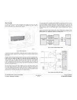
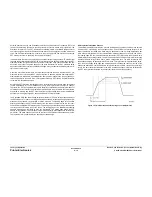
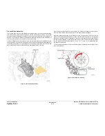
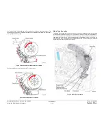
Figure 17 Drum Maintenance
Printhead Maintenance
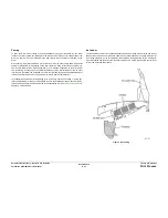
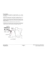
To perform a Printhead maintenance cycle, the Printhead is first tilted away from the Drum to
allow the Wiper Blade to pass by. The Wiper Blade is then raised in front of the Printhead. The
media path drive governs wiper movement when it engages the Head Maintenance Clutch on
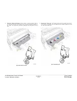
the exit shaft of the system. The Purge Pump applies pressure to the ink reservoir for approxi-
mately 2.5 seconds. Valves in the reservoir seal when pressure is applied. The pressurization
ejects a small amount of ink from the jets. Following the pressure purge, the Printhead tilts into
the Wiper Blade and the wipe cycle begins. The pump runs again with the Solenoid for approx-
imately 30 seconds, creating a neutral balance between pressure and ink. The Wiper Blade
lowers and wipes excess ink from the jets into the Waste Tray. A proper purge covers the
length of the Waste Tray with a single layer of ink about 20 mm wide.
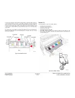
The level of the ink in the reservoir is kept constant. If the purge tubing is pinched, the Print-
head may not purge properly. In addition, because the purge tubing also acts as a vent to
atmosphere when not purging, a more serious failure can occur if the ink overfills and the res-
ervoir cannot vent properly.
Summary of Contents for COLORQUBE 8570
Page 1: ...ColorQube 8570 8870 Printer ColorQube 8570 8870 Service Manual Xerox Internal Use Only...
Page 2: ......
Page 423: ......

