February 2013
4-405
ColorQube® 9303 Family
ADJ 12.5-171
Repairs/Adjustments
c.
Select
dC131
NVM Read / Write.
d.
Enter NVMID 12-006 BookMkrTampRdyOff-set.
e.
Select Read / Write and increase the value by 8.
f.
Select Save, select OK, select Close, select Exit.
Adjustment
1.
Do the following:
a.
Enter Service Mode
GP 1
.
b.
Select Adjustment Routines.
c.
Select
dC131
NVM Read / Write.
d.
Enter NVMID 12-006 BookMkrTampRdyOff-set.
e.
Select Read / Write and enter the new value to correct the error found during the
check. Increasing the value lengthens the tamping stroke (tamps to a narrower
dimension between the tampers. Decreasing the value shortens the tamping stroke
(tamps to a wider dimension between the tampers). One step = 0.53 mm.
f.
Select Save, select OK, select Close, select Exit.
2.
Repeat the check to ensure the tampers are set correctly.
3.
When the tamper travel is correct, do the following:
a.
Enter Service Mode
GP 1
.
b.
Select Adjustment Routines.
c.
Select
dC131
NVM Read / Write.
d.
Enter NVMID 12-006 BookMkrTampRdyOff-set.
e.
Select Read / Write and increase the value by 8.
f.
Select Save, select OK, select Close, select Exit.
4.
Switch the machine off then on,
GP 14
.
8.5 X 11 Inch Procedure
Check
1.
Open the HVF BM front door and insert an interlock cheater into the front door interlock
switch.
2.
Fully pull out the booklet maker and release the jam clearance handle
PL 12.150 Item 8
,
fully open the paper guide
PL 12.150 Item 7
.
3.
Do the following:
a.
Enter Service Mode
GP 1
.
b.
Select Adjustment Routines.
c.
Select
dC131
NVM Read / Write.
d.
Enter NVMID 12-006 BookMkrTampRdyOff-set.
e.
Select Read/Write and reduce the original value by 19.
f.
Select Save, select OK, select Close, select Exit.
4.
Enter Diagnostic Routine
dC330
code 12-255 BM Backstop Motor, select Start, allow the
backstop to raise to the receive position (where it will pause), select Stop.
5.
Enter Diagnostic Routine
dC330
code 12-256 BM tamper 1 motor. Select Start to run the
tamper motor, allow the tampers to move into the tamped position (where they will pause),
select Stop.
6.
Insert a single sheet of 8.5 X 11 inch paper, short edge downward into the booklet maker
compiling area, so that it rests on the backstop and is located between the two tampers
7.
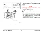
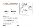
Bias the sheet towards the rear of the machine until the sheet touches the rear tamper,
Figure 1
.
8.
Observe the position of the sheet between the tampers,
Figure 1
.
•
If the sheet cannot reach the backstop because the tampers are too close together,
the NVM value will need to be decreased to move the tampers further apart, perform
the adjustment.
•
If the front tamper is not within 0.5 mm (0.02 inch) of the sheet edge without touching
the sheet, the NVM value will need to be increased to move the tampers closer
together, perform the adjustment.
•
If the tampers are in the correct position, within 0.5 mm (0.02 inch) of the sheet edge
without touching the sheet, do the following:
a.
Enter Service Mode
GP 1
.
b.
Select Adjustment Routines.
c.
Select
dC131
NVM Read / Write.
d.
Enter NVMID 12-006 BookMkrTampRdyOff-set.
e.
Select Read / Write and increase the value by 19.
f.
Select Save, select OK, select Close, select Exit.
Adjustment
1.
Do the following:
a.
Enter Service Routine
GP 1
.
b.
Select Adjustment Routines.
c.
Select
dC131
NVM Read / Write.
d.
Enter NVMID 12-006 BookMkrTampRdyOff-set.
e.
Select Read / Write and enter the new value to correct the error found during the
check. Increasing the value lengthens the tamping stroke (tamps to a narrower
dimension between the tampers. Decreasing the value shortens the tamping stroke
(tamps to a wider dimension between the tampers). One step = 0.53 mm.
f.
Select Save, select OK, select Close, select Exit.
2.
Repeat the check to ensure the tampers are set correctly.
3.
When the tamper travel is correct, do the following:
a.
Enter Service Mode
GP 1
.
b.
Select Adjustment Routines.
c.
Select
dC131
NVM Read / Write.
d.
Enter NVMID 12-006 BookMkrTampRdyOff-set.
e.
Select Read / Write and increase the value by 19.
f.
Select Save, select OK, select Close, select Exit.
4.
Switch the machine off then on,
GP 14
.
Summary of Contents for ColorQube 9303 Series
Page 1: ...Xerox ColorQube 9303 Family Service Manual 708P90290 February 2013...
Page 4: ...February 2013 ii ColorQube 9303 Family Introduction...
Page 18: ...February 2013 1 2 ColorQube 9303 Family Service Call Procedures...
Page 92: ...February 2013 2 68 ColorQube 9303 Family 05F Status Indicator RAPs...
Page 104: ...February 2013 2 80 ColorQube 9303 Family 12 701 00 65 Status Indicator RAPs...
Page 200: ...February 2013 2 176 ColorQube 9303 Family 12N 171 Status Indicator RAPs...
Page 292: ...February 2013 2 268 ColorQube 9303 Family 16D Status Indicator RAPs...
Page 320: ...February 2013 2 296 ColorQube 9303 Family 42 504 00 42 505 00 Status Indicator RAPs...
Page 500: ...February 2013 2 476 ColorQube 9303 Family 94B Status Indicator RAPs...
Page 648: ...February 2013 3 2 ColorQube 9303 Family Image Quality...
Page 653: ...February 2013 3 7 ColorQube 9303 Family IQ 1 Image Quality Figure 1 IQ defects 1...
Page 654: ...February 2013 3 8 ColorQube 9303 Family IQ 1 Image Quality Figure 2 IQ defects 2...
Page 655: ...February 2013 3 9 ColorQube 9303 Family IQ 1 Image Quality Figure 3 IQ defects 3...
Page 656: ...February 2013 3 10 ColorQube 9303 Family IQ 1 Image Quality Figure 4 IQ defects 4...
Page 657: ...February 2013 3 11 ColorQube 9303 Family IQ 1 Image Quality Figure 5 IQ defects 5...
Page 658: ...February 2013 3 12 ColorQube 9303 Family IQ 1 Image Quality Figure 6 IQ defects 6...
Page 660: ...February 2013 3 14 ColorQube 9303 Family IQ 1 Image Quality Figure 9 IQ defects 9...
Page 661: ...February 2013 3 15 ColorQube 9303 Family IQ 1 Image Quality Figure 10 IQ defects 10...
Page 662: ...February 2013 3 16 ColorQube 9303 Family IQ 1 Image Quality Figure 11 IQ defects 11...
Page 663: ...February 2013 3 17 ColorQube 9303 Family IQ 1 Image Quality Figure 12 IQ defects 12...
Page 664: ...February 2013 3 18 ColorQube 9303 Family IQ 1 Image Quality Figure 13 IQ defects 13...
Page 728: ...February 2013 3 82 ColorQube 9303 Family IQ 29 IQ 30 Image Quality...
Page 736: ...February 2013 3 90 ColorQube 9303 Family TP 15 Image Quality Figure 2 Media path test pages...
Page 758: ...February 2013 3 112 ColorQube 9303 Family IQS 7 IQS 8 Image Quality...
Page 778: ...February 2013 4 20 ColorQube 9303 Family REP 1 9 Repairs Adjustments...
Page 794: ...February 2013 4 36 ColorQube 9303 Family REP 3 10 Repairs Adjustments...
Page 1144: ...February 2013 4 386 ColorQube 9303 Family REP 94 1 Repairs Adjustments...
Page 1176: ...February 2013 4 418 ColorQube 9303 Family ADJ 62 3 ADJ 62 4 Repairs Adjustments...
Page 1182: ...February 2013 4 424 ColorQube 9303 Family ADJ 75 3 Repairs Adjustments...
Page 1184: ...February 2013 4 426 ColorQube 9303 Family ADJ 82 1 Repairs Adjustments...
Page 1186: ...February 2013 4 428 ColorQube 9303 Family ADJ 91 1 Repairs Adjustments...
Page 1552: ...February 2013 6 260 ColorQube 9303 Family dC140 General Procedures Information...
Page 1576: ...February 2013 6 284 ColorQube 9303 Family dC640 General Procedures Information...
Page 1578: ...February 2013 6 286 ColorQube 9303 Family dC708 dC715 General Procedures Information...
Page 1600: ...February 2013 7 2 ColorQube 9303 Family Wiring Data...
Page 1696: ...February 2013 8 2 ColorQube 9303 Family Principles of Operation...
Page 1808: ...February 2013 8 114 ColorQube 9303 Family Principles of Operation...
Page 1809: ...XEROX EUROPE...
Page 1810: ...XEROX EUROPE...
Page 1811: ...XEROX EUROPE...
Page 1812: ...XEROX EUROPE...


