February 2013
2-27
ColorQube® 9303 Family
01E
Status Indicator RAPs
–
Enclosure Fan,
PL 1.15 Item 6
.
–
Marking unit cooling fan,
PL 1.15 Item 23
.
–
Abatement fan assembly,
PL 94.20 Item 11
.
–
Cleaning unit,
PL 94.10 Item 21
.
–
Stripper Jam Clearance LED assembly,
PL 10.10 Item 10
–
Registration/preheat Interface PWB,
PL 88.10 Item 10
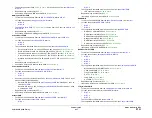
•
Repair the wiring as necessary,
REP 1.1
.
•
If necessary, install a new drum driver PWB,
PL 1.15 Item 4
, or one of the items in the list
above.
Cleaning Unit
•
To view the +12V distribution from the
drum driver PWB
, refer to
WD 9.4
.
•
For +12V faults on the cleaning unit PWB, refer to
WD 9.19
.
•
Repair the wiring as necessary,
REP 1.1
.
•
If necessary, install a new cleaning unit,
PL 94.10 Item 21
.
NOTE: The cleaning unit PWB is not spared individually, the next highest assembly is the
cleaning unit.
Media Path Driver PWB
•
To view the +12V distribution from the
power supply unit
, refer to
WD 1.5
.
•
For +12V faults on the
media path driver PWB
, refer to:
–
WD 8.1
–
WD 8.5
•
The components that follow are driven from +12V from the
media path driver PWB
:
–
Exit illuminator,
PL 10.15 Item 16
.
–
Horizontal illuminator,
PL 82.15 Item 11
.
–
Registration/preheat illuminator PWB,
PL 82.15 Item 17
.
–
Registration/preheat interface PWB,
PL 88.10 Item 10
.
•
Repair the wiring as necessary,
REP 1.1
.
•
If necessary, install a new media path driver PWB,
PL 1.15 Item 5
, or one of the items in
the list above.
Registration/Pre-heat Interface PWB
•
To view the +12V distribution from the
drum driver PWB
, refer to
WD 9.2
.
•
To view +12 V distribution from
media path driver PWB
, refer to
WD 8.1
.
•
For +12V faults on the registration/pre-heat interface PWB, refer to
WD 8.6
.
•
The components that follow are driven from +12V from the reg/preheat interface PWB:
–
Registration scan bar Q89-005,
PL 88.10 Item 2
.
–
Registration/preheat air pumps MOT88-008,
PL 88.10 Item 5
.
•
Repair the wiring as necessary,
REP 1.1
.
•
If necessary, install a new registration/pre-heat interface PWB,
PL 88.10 Item 10
, or one
of the items in the list above
Power Distribution PWB
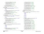
•
To view the +12V distribution from the
power supply unit
, refer to
WD 1.5
.
•
For +12V faults on the
power distribution PWB
, refer to:
–
WD 1.6
–
WD 1.7
•
Check for +12V on both sides of fuse F2 on the
power distribution PWB
. If +12V is not
present, check the wiring between PJ8 pin 11 on the
power distribution PWB
and PJ920
pin 5 on the
scanner PWB
.
•
Repair the wiring as necessary,
REP 1.1
.
•
If necessary, install a new power distribution PWB,
PL 3.11 Item 1
.
Single Board Controller PWB
•
To view the +3.3V distribution from the
power distribution PWB
, refer to
WD 1.6
.
•
For +3.3V faults on the
single board controller PWB
, refer to:
–
WD 3.1
–
WD 3.2
•
If necessary repair the wiring,
REP 1.1
or install a new DADH/IIT power comms harness,
PL 62.16 Item 7
.
•
If necessary, install a new single board controller PWB,
PL 3.11 Item 13
.
Scanner PWB
•
To view the +12V distribution from the
power distribution PWB
, refer to
WD 1.7
.
•
For +12V faults on the
scanner PWB
, refer to:
–
WD 6.1
–
WD 6.3
•
The scan carriage,
PL 62.15 Item 6
is driven from +12V from the
scanner PWB
:
•
Repair the wiring as necessary,
REP 1.1
.
•
If necessary, install a new scanner PWB,
PL 62.16 Item 8
.
Full Width Array
•
To view the +12V distribution from the
scanner PWB
, refer to
WD 6.3
.
•
For +12V faults on the full width array, refer to
WD 6.3
.
•
Repair the wiring as necessary,
REP 1.1
.
•
If necessary, install a new scan carriage assembly,
PL 62.15 Item 1
.
UI PWB
•
To view the +12V distribution from the
single board controller PWB
, refer to
WD 3.2
•
For +12V faults on the
UI PWB
, refer to
WD 3.2
.
•
If necessary repair the wiring,
REP 1.1
.
•
If necessary, install a new user interface control PWB,
PL 2.10 Item 2
or user interface
status PWB,
PL 2.10 Item 4
.
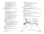
Quad Wave Amp PWB
•
To view the +12V distribution from the
IME controller PWB
, refer to
WD 9.5
.
•
For +12V faults on
quad wave amp PWB
, refer to
WD 9.13
.
•
Repair the wiring as necessary,
REP 1.1
.
•
If necessary, install a new quad wave amp PWB,
PL 92.10 Item 3
.
Printheads 1 to 4
•
To view the +12 V distribution from the
IME controller PWB
, refer to
WD 9.5
and
WD 9.6
.
•
For +12V faults on the printhead, refer to
WD 9.20
and
WD 9.21
.
•
If necessary, install a new printhead
PL 91.20 Item 2
or
PL 91.25 Item 2
.
Summary of Contents for ColorQube 9303 Series
Page 1: ...Xerox ColorQube 9303 Family Service Manual 708P90290 February 2013...
Page 4: ...February 2013 ii ColorQube 9303 Family Introduction...
Page 18: ...February 2013 1 2 ColorQube 9303 Family Service Call Procedures...
Page 92: ...February 2013 2 68 ColorQube 9303 Family 05F Status Indicator RAPs...
Page 104: ...February 2013 2 80 ColorQube 9303 Family 12 701 00 65 Status Indicator RAPs...
Page 200: ...February 2013 2 176 ColorQube 9303 Family 12N 171 Status Indicator RAPs...
Page 292: ...February 2013 2 268 ColorQube 9303 Family 16D Status Indicator RAPs...
Page 320: ...February 2013 2 296 ColorQube 9303 Family 42 504 00 42 505 00 Status Indicator RAPs...
Page 500: ...February 2013 2 476 ColorQube 9303 Family 94B Status Indicator RAPs...
Page 648: ...February 2013 3 2 ColorQube 9303 Family Image Quality...
Page 653: ...February 2013 3 7 ColorQube 9303 Family IQ 1 Image Quality Figure 1 IQ defects 1...
Page 654: ...February 2013 3 8 ColorQube 9303 Family IQ 1 Image Quality Figure 2 IQ defects 2...
Page 655: ...February 2013 3 9 ColorQube 9303 Family IQ 1 Image Quality Figure 3 IQ defects 3...
Page 656: ...February 2013 3 10 ColorQube 9303 Family IQ 1 Image Quality Figure 4 IQ defects 4...
Page 657: ...February 2013 3 11 ColorQube 9303 Family IQ 1 Image Quality Figure 5 IQ defects 5...
Page 658: ...February 2013 3 12 ColorQube 9303 Family IQ 1 Image Quality Figure 6 IQ defects 6...
Page 660: ...February 2013 3 14 ColorQube 9303 Family IQ 1 Image Quality Figure 9 IQ defects 9...
Page 661: ...February 2013 3 15 ColorQube 9303 Family IQ 1 Image Quality Figure 10 IQ defects 10...
Page 662: ...February 2013 3 16 ColorQube 9303 Family IQ 1 Image Quality Figure 11 IQ defects 11...
Page 663: ...February 2013 3 17 ColorQube 9303 Family IQ 1 Image Quality Figure 12 IQ defects 12...
Page 664: ...February 2013 3 18 ColorQube 9303 Family IQ 1 Image Quality Figure 13 IQ defects 13...
Page 728: ...February 2013 3 82 ColorQube 9303 Family IQ 29 IQ 30 Image Quality...
Page 736: ...February 2013 3 90 ColorQube 9303 Family TP 15 Image Quality Figure 2 Media path test pages...
Page 758: ...February 2013 3 112 ColorQube 9303 Family IQS 7 IQS 8 Image Quality...
Page 778: ...February 2013 4 20 ColorQube 9303 Family REP 1 9 Repairs Adjustments...
Page 794: ...February 2013 4 36 ColorQube 9303 Family REP 3 10 Repairs Adjustments...
Page 1144: ...February 2013 4 386 ColorQube 9303 Family REP 94 1 Repairs Adjustments...
Page 1176: ...February 2013 4 418 ColorQube 9303 Family ADJ 62 3 ADJ 62 4 Repairs Adjustments...
Page 1182: ...February 2013 4 424 ColorQube 9303 Family ADJ 75 3 Repairs Adjustments...
Page 1184: ...February 2013 4 426 ColorQube 9303 Family ADJ 82 1 Repairs Adjustments...
Page 1186: ...February 2013 4 428 ColorQube 9303 Family ADJ 91 1 Repairs Adjustments...
Page 1552: ...February 2013 6 260 ColorQube 9303 Family dC140 General Procedures Information...
Page 1576: ...February 2013 6 284 ColorQube 9303 Family dC640 General Procedures Information...
Page 1578: ...February 2013 6 286 ColorQube 9303 Family dC708 dC715 General Procedures Information...
Page 1600: ...February 2013 7 2 ColorQube 9303 Family Wiring Data...
Page 1696: ...February 2013 8 2 ColorQube 9303 Family Principles of Operation...
Page 1808: ...February 2013 8 114 ColorQube 9303 Family Principles of Operation...
Page 1809: ...XEROX EUROPE...
Page 1810: ...XEROX EUROPE...
Page 1811: ...XEROX EUROPE...
Page 1812: ...XEROX EUROPE...


