February 2013
2-37
ColorQube® 9303 Family
01L
Status Indicator RAPs
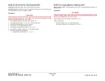
01L 0V Distribution RAP
Use this RAP to diagnose 0V faults.
Procedure
WARNING
Ensure that the electricity to the machine is switched off while performing tasks that do
not need electricity. Refer to
GP 14
. Disconnect the power cord. Electricity can cause
death or injury. Moving parts can cause injury.
Important: 0V return lines are connected together and to the chassis, both inside the
power supply units and at the PWB’s.
•
To measure the continuity of a 0V line between the
power supply unit
and a PWB, isolate
the line concerned by disconnecting the PJs at both ends. In this way there will be no mis-
leading parallel paths. As necessary, repair the wiring,
REP 1.1
or install a new harness.
The same applies between the
power distribution PWB
and other PWB’s.
•
To check the connection of a 0V line to chassis via the
power supply unit
, connect the PJ
at the
power supply unit
only, disconnect from the PWB, and measure the continuity to the
chassis. As necessary, repair the wiring,
REP 1.1
or install a new power supply unit,
PL
1.15 Item 2
.
•
To check the connection of a 0V line to chassis via the PWB, connect the power PJ at the
PWB only, disconnect from the
power supply unit
, and measure the continuity to the chas-
sis. If necessary repair the wiring or install a new PWB.
•
To check the 0V line between a PWB and a component, (sensor, motor, etc.), disconnect
the PWB PJ, then check the wiring for condition, short circuits, open circuits etc. As nec-
essary, repair the wiring,
REP 1.1
, install a new harness, component or PWB.
This procedure lists the wiring diagrams that show the occurrence of 0V lines. Select the sus-
pect area from the list below, check the wiring for condition, short circuits and open circuits.
Repair the wiring as necessary,
REP 1.1
or install a new harness or faulty component.
•
Power Supply Unit
•
Power Distribution PWB
•
Single Board Controller PWB
•
UI Control PWB, Touch Screen and UI Status PWB
•
Foreign Device Interface PWB
•
DADH PWB
•
Scanner PWB
•
Tray 5 Control PWB
•
3 Tray Module PWB
•
Media Path Driver PWB
•
Drum Driver PWB
•
IME Controller PWB
•
Marking Unit Heater PWB
•
Marking Unit Driver PWB
•
Quad Wave Amp PWB
•
Solenoid Patch PWB
•
Ink Load Entry PWB
•
Cleaning Unit PWB
•
Printheads 1, 2, 3 and 4 PWB’s
•
IOD Pre-amplifier PWB
•
LCSS PWB
•
HVF Control PWB
•
BM PWB (Booklet maker)
•
Tri-folder PWB
•
Inserter PWB
•
OCT PWB
Power Supply Unit
•
Refer to
WD 1.3
,
WD 1.4
and
WD 1.5.
•
Repair the wiring as necessary,
REP 1.1
.
•
If necessary install a new power supply unit,
PL 1.15 Item 2
.
Power Distribution PWB
•
Refer to
WD 1.6
and
WD 1.7
.
•
Repair the wiring as necessary,
REP 1.1
.
•
If necessary install a new power supply unit,
PL 1.15 Item 2
.
Single Board Controller PWB
•
Refer to
WD 3.1
,
WD 3.2
and
WD 3.3
.
•
Repair the wiring as necessary,
REP 1.1
.
•
If necessary, install a new single board controller PWB,
PL 3.11 Item 13
or associated
components.
UI Control PWB, Touch Screen and UI Status PWB
•
Refer to
WD 3.1
. If necessary, install new components from the list that follows:
–
UI control PWB,
PL 2.10 Item 2
.
–
Touch screen,
PL 2.10 Item 3
.
–
UI status PWB,
PL 2.10 Item 4
.
–
LCD to PWB harness,
PL 2.10 Item 11
.
–
UI control to UI status harness,
PL 2.10 Item 9
.
•
Repair the wiring as necessary,
REP 1.1
.
•
If necessary, install a new user interface control PWB.
•
If necessary, install a new touch screen,
PL 2.10 Item 3
.
•
If necessary, install a new user interface status PWB,
PL 2.10 Item 4
.
Foreign Device Interface PWB
•
Refer to
WD 3.3
.
•
Repair the wiring as necessary,
REP 1.1
•
If necessary, install a new foreign device interface PWB,
PL 3.11 Item 23
, or associated
components.
DADH PWB
•
Refer to
WD 5.1
and
WD 5.2
•
Repair the wiring as necessary,
REP 1.1
•
If necessary, install a new DADH PWB,
PL 5.10 Item 5
, or associated components.
Scanner PWB
•
Refer to
WD 6.1
,
WD 6.2
and
WD 6.3
•
Repair the wiring as necessary,
REP 1.1
•
If necessary, install a new scanner PWB,
PL 62.16 Item 8
, or associated components.
Tray 5 Control PWB
•
Refer to
WD 7.1
and
WD 7.2
Summary of Contents for ColorQube 9303 Series
Page 1: ...Xerox ColorQube 9303 Family Service Manual 708P90290 February 2013...
Page 4: ...February 2013 ii ColorQube 9303 Family Introduction...
Page 18: ...February 2013 1 2 ColorQube 9303 Family Service Call Procedures...
Page 92: ...February 2013 2 68 ColorQube 9303 Family 05F Status Indicator RAPs...
Page 104: ...February 2013 2 80 ColorQube 9303 Family 12 701 00 65 Status Indicator RAPs...
Page 200: ...February 2013 2 176 ColorQube 9303 Family 12N 171 Status Indicator RAPs...
Page 292: ...February 2013 2 268 ColorQube 9303 Family 16D Status Indicator RAPs...
Page 320: ...February 2013 2 296 ColorQube 9303 Family 42 504 00 42 505 00 Status Indicator RAPs...
Page 500: ...February 2013 2 476 ColorQube 9303 Family 94B Status Indicator RAPs...
Page 648: ...February 2013 3 2 ColorQube 9303 Family Image Quality...
Page 653: ...February 2013 3 7 ColorQube 9303 Family IQ 1 Image Quality Figure 1 IQ defects 1...
Page 654: ...February 2013 3 8 ColorQube 9303 Family IQ 1 Image Quality Figure 2 IQ defects 2...
Page 655: ...February 2013 3 9 ColorQube 9303 Family IQ 1 Image Quality Figure 3 IQ defects 3...
Page 656: ...February 2013 3 10 ColorQube 9303 Family IQ 1 Image Quality Figure 4 IQ defects 4...
Page 657: ...February 2013 3 11 ColorQube 9303 Family IQ 1 Image Quality Figure 5 IQ defects 5...
Page 658: ...February 2013 3 12 ColorQube 9303 Family IQ 1 Image Quality Figure 6 IQ defects 6...
Page 660: ...February 2013 3 14 ColorQube 9303 Family IQ 1 Image Quality Figure 9 IQ defects 9...
Page 661: ...February 2013 3 15 ColorQube 9303 Family IQ 1 Image Quality Figure 10 IQ defects 10...
Page 662: ...February 2013 3 16 ColorQube 9303 Family IQ 1 Image Quality Figure 11 IQ defects 11...
Page 663: ...February 2013 3 17 ColorQube 9303 Family IQ 1 Image Quality Figure 12 IQ defects 12...
Page 664: ...February 2013 3 18 ColorQube 9303 Family IQ 1 Image Quality Figure 13 IQ defects 13...
Page 728: ...February 2013 3 82 ColorQube 9303 Family IQ 29 IQ 30 Image Quality...
Page 736: ...February 2013 3 90 ColorQube 9303 Family TP 15 Image Quality Figure 2 Media path test pages...
Page 758: ...February 2013 3 112 ColorQube 9303 Family IQS 7 IQS 8 Image Quality...
Page 778: ...February 2013 4 20 ColorQube 9303 Family REP 1 9 Repairs Adjustments...
Page 794: ...February 2013 4 36 ColorQube 9303 Family REP 3 10 Repairs Adjustments...
Page 1144: ...February 2013 4 386 ColorQube 9303 Family REP 94 1 Repairs Adjustments...
Page 1176: ...February 2013 4 418 ColorQube 9303 Family ADJ 62 3 ADJ 62 4 Repairs Adjustments...
Page 1182: ...February 2013 4 424 ColorQube 9303 Family ADJ 75 3 Repairs Adjustments...
Page 1184: ...February 2013 4 426 ColorQube 9303 Family ADJ 82 1 Repairs Adjustments...
Page 1186: ...February 2013 4 428 ColorQube 9303 Family ADJ 91 1 Repairs Adjustments...
Page 1552: ...February 2013 6 260 ColorQube 9303 Family dC140 General Procedures Information...
Page 1576: ...February 2013 6 284 ColorQube 9303 Family dC640 General Procedures Information...
Page 1578: ...February 2013 6 286 ColorQube 9303 Family dC708 dC715 General Procedures Information...
Page 1600: ...February 2013 7 2 ColorQube 9303 Family Wiring Data...
Page 1696: ...February 2013 8 2 ColorQube 9303 Family Principles of Operation...
Page 1808: ...February 2013 8 114 ColorQube 9303 Family Principles of Operation...
Page 1809: ...XEROX EUROPE...
Page 1810: ...XEROX EUROPE...
Page 1811: ...XEROX EUROPE...
Page 1812: ...XEROX EUROPE...


