


June 2014
vi
Xerox® Phaser® 3020 Printer Service Manual
Introduction
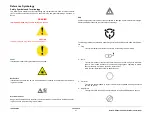
Reference Symbology
Safety Symbols and Terminology
The following are examples of the terminology and symbols that are used in this documenta-
tion for an Electrostatic Device Caution, Laser Warning, and general Warnings, Cautions, or
Notes.
WARNING
Improper operation may result in injury to a person.
CAUTION
Improper operation may result in machine damage.
Laser
Indicates that Laser safety precautions must be used.
Hot Surface
Indicates that a surface can be hot. Use caution when reaching in the machine to avoid touch-
ing the hot surface.
Electrical Current
Danger label indicates where electrical currents travel when the machine is closed and operat-
ing. Use caution when reaching in the machine.
ESD
Certain components in this product are susceptible to damage from Electrostatic Discharge.
Observe all ESD procedures to avoid component damage.
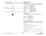
The following reference symbols are used throughout the Xerox® Phaser® 3020 Service Man-
ual.
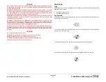
1.
Flag
•
This symbol indicates a reference point into a circuit diagram from a RAP.
2.
Note
•
This symbol is used to refer to notes that are found on the same page of a circuit dia-
gram. A note is used whenever it is necessary to highlight an operating or mainte-
nance procedure, a practice, condition, or statement.
•
Hints or other information that may assist the user.
3.
Parts List
•
This symbol, example (PL2.1), refers to the Parts List exploded view page where the
part can be found.
4.
Adjustment
•
This symbol refers to an adjustment procedure in the Repair/Adjustments section.
Summary of Contents for Phaser 3020
Page 1: ...Xerox Phaser 3020 Service Manual 702P02829 June 2014 Initial Issue ...
Page 2: ......
Page 4: ...June 2014 2 Xerox Phaser 3020 Printer Service Manual Initial Issue ...
Page 6: ...June 2014 ii Xerox Phaser 3020 Printer Service Manual Introduction ...
Page 18: ...June 2014 1 2 Xerox Phaser 3020 Printer Service Manual Service Call Procedures ...
Page 24: ...June 2014 2 2 Xerox Phaser 3020 Printer Service Manual Status Indicator RAPs ...
Page 36: ...June 2014 3 2 Xerox Phaser 3020 Printer Service Manual Image Quality ...
Page 46: ...June 2014 3 12 Xerox Phaser 3020 Printer Service Manual IQ11 Image Quality ...
Page 48: ...June 2014 4 2 Xerox Phaser 3020 Printer Service Manual Repairs ...
Page 74: ...June 2014 4 28 Xerox Phaser 3020 Printer Service Manual REP 1 18 Repairs ...
Page 76: ...June 2014 5 2 Xerox Phaser 3020 Printer Service Manual Parts List ...
Page 88: ...June 2014 6 2 Xerox Phaser 3020 Printer Service Manual General Procedures and Information ...
Page 108: ...Xerox Phaser 3020 Printer Service Manual June 2014 BSDs THIS PAGE INTENTIONALLY BLANK ...


