


8-16
Phaser 34
25
Laser Printer Service Manual
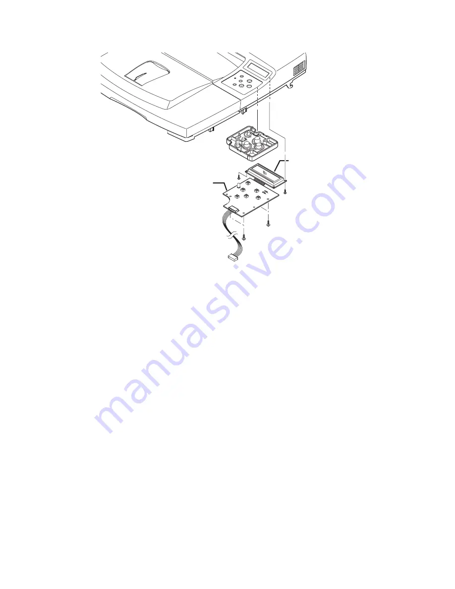
3.
Remove the 6 screws that secure the Front Panel Assembly to the Top Cover and
remove the Front Panel Assembly.
Cover Open Interlock Switch (PL 9.2.1.16)
Note
It is not mandatory to remove the Top Cover to access the interlock switch,
however the Right Cover must be removed in order to disconnect the
interlock switch connector CN 2 from the Cover Interconnect Board.
Routing the switch cable to the Main Board is easier with the Top Cover
removed.
1.
Remove the Print Cartridge (page 8-4) and protect it from light.
2.
Remove the Top Cover Assembly (page 8-9).
3.
Open the front section of the Top Cover to access the Interlock Switch cover.
1.
Button Panel
2.
LCD Panel
1
2
-
Summary of Contents for Phaser 3425
Page 1: ...Service Manual P h a s e r L a s e r P r i n t e r 3425 ...
Page 2: ......
Page 14: ...xii Phaser 3425 Laser Printer ...
Page 20: ...xviii Phaser 3425 Laser Printer ...
Page 29: ...General Information 1 9 Consumables 1 Print Cartridge 1 ...
Page 48: ...2 14 Phaser 3425 Laser Printer Service Manual ...
Page 93: ...6 Chapter Adjustments and Calibrations In this chapter Margin Calibration Resetting NVRAM ...
Page 98: ...7 4 Phaser 3425 Laser Printer Service Manual ...
Page 144: ...8 46 Phaser 3425 Laser Printer Service Manual ...
Page 145: ...9 Chapter Parts Lists In this chapter Using the Parts List Print Engine Parts Xerox Supplies ...
Page 175: ...10 6 Phaser 3425 Laser Printer Service Manual ...
Page 179: ......
Page 180: ......


