


Service Parts Disassembly
8-17
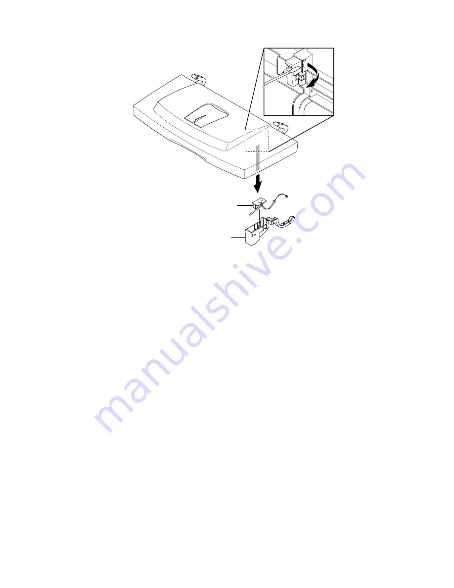
4.
Using a small flat blade screwdriver, pry outward to release the retainers (6) that
secure the interlock switch cap, and pull the cap free of the cover.
5.
Remove the Cover Open Interlock Switch
NIC Board (PL 9.1.41)
1.
Remove the Right Cover Assembly (page 8-7).
Caution
Observe proper ESD procedures when removing or replacing any circuit
boards in the printer. Refer to "General Notes on Disassembly" on page 8-3.
2.
Remove 2 thumbscrews securing the NIC Board to the rear edge of the Main
Board mounting bracket.
3.
Pull up on the front edge of the NIC Board to remove it from the connector
(CN 9) on the Main Board and remove the NIC Board to the right.
1.
Interlock Switch
2.
Switch Cap
1
2
-
Summary of Contents for Phaser 3425
Page 1: ...Service Manual P h a s e r L a s e r P r i n t e r 3425 ...
Page 2: ......
Page 14: ...xii Phaser 3425 Laser Printer ...
Page 20: ...xviii Phaser 3425 Laser Printer ...
Page 29: ...General Information 1 9 Consumables 1 Print Cartridge 1 ...
Page 48: ...2 14 Phaser 3425 Laser Printer Service Manual ...
Page 93: ...6 Chapter Adjustments and Calibrations In this chapter Margin Calibration Resetting NVRAM ...
Page 98: ...7 4 Phaser 3425 Laser Printer Service Manual ...
Page 144: ...8 46 Phaser 3425 Laser Printer Service Manual ...
Page 145: ...9 Chapter Parts Lists In this chapter Using the Parts List Print Engine Parts Xerox Supplies ...
Page 175: ...10 6 Phaser 3425 Laser Printer Service Manual ...
Page 179: ......
Page 180: ......


