Service Parts Disassembly
8-19
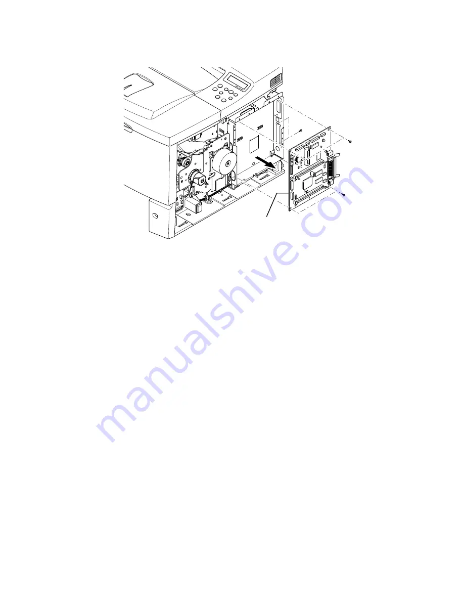
4.
Position the retainers on the parallel port connector straight out from the
connector for removal. Move the board toward the front of the printer so the
connectors clear the bracket and remove the Main Board to the right.
Note
NVRAM parameters are not transferable to the replacement board. These
parameters include Serial Number and copy count. Serial Number can be
reinstalled via CentreWare if the NIC Board is installed or via a
downloadable PJL command.
Replacement Notes
Note
When reinstalling the Main Board, the short machine screw goes in the top
right corner of the board.
Main Drive Assembly (PL 9.1.11)
1.
Remove the Right Cover Assembly (page 8-7).
2.
Disconnect CN 14 connecting the Registration Clutch to the Connector Board
(see "Map 2 Connector Board" on page 10-4).
3.
Disconnect CN 1 from the Main Drive Assembly. The cable connects to CN 11
on the Main Board (see "Print Engine Interconnect Diagram" on page 10-2).
4.
Remove 1 screw securing the AC Terminal Cover to the Main Drive Assembly
and remove the cover.
1
-
Summary of Contents for Phaser 3425
Page 1: ...Service Manual P h a s e r L a s e r P r i n t e r 3425 ...
Page 2: ......
Page 14: ...xii Phaser 3425 Laser Printer ...
Page 20: ...xviii Phaser 3425 Laser Printer ...
Page 29: ...General Information 1 9 Consumables 1 Print Cartridge 1 ...
Page 48: ...2 14 Phaser 3425 Laser Printer Service Manual ...
Page 93: ...6 Chapter Adjustments and Calibrations In this chapter Margin Calibration Resetting NVRAM ...
Page 98: ...7 4 Phaser 3425 Laser Printer Service Manual ...
Page 144: ...8 46 Phaser 3425 Laser Printer Service Manual ...
Page 145: ...9 Chapter Parts Lists In this chapter Using the Parts List Print Engine Parts Xerox Supplies ...
Page 175: ...10 6 Phaser 3425 Laser Printer Service Manual ...
Page 179: ......
Page 180: ......