


Service Parts Disassembly
8-27
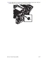
8.
Using a small flat blade screwdriver spread the plastic latch hooks on the bottom
of the bearing while pulling the left end of the Transport Roller Shaft Assembly
to the rear.
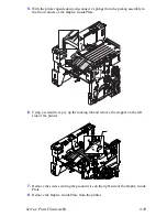
9.
Continue pulling the Transport Roller Shaft Assembly to the rear to remove it
from the center bearing.
10.
Press down on the tab that secures the Transport Roller Shaft Assembly gear to
the shaft and remove the gear.
11.
Repeat the procedure for the bearing on the right end of the Transport Roller
Shaft Assembly and remove the shaft.
12.
Slide the bearings off both ends of the Transport Roller Shaft Assembly.
Note
The bearings can be left in place on the shaft unless they or the shaft are
being replaced.
Note
On reassembly, ensure that the Output Full Sensor actuator moves freely.
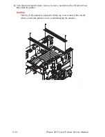
Laser Assembly (PL 9.1.16)
1.
Remove the Print Cartridge (page 8-4) and protect it from light.
2.
Remove the Top Cover Assembly (page 8-9).
1
-
Summary of Contents for Phaser 3425
Page 1: ...Service Manual P h a s e r L a s e r P r i n t e r 3425 ...
Page 2: ......
Page 14: ...xii Phaser 3425 Laser Printer ...
Page 20: ...xviii Phaser 3425 Laser Printer ...
Page 29: ...General Information 1 9 Consumables 1 Print Cartridge 1 ...
Page 48: ...2 14 Phaser 3425 Laser Printer Service Manual ...
Page 93: ...6 Chapter Adjustments and Calibrations In this chapter Margin Calibration Resetting NVRAM ...
Page 98: ...7 4 Phaser 3425 Laser Printer Service Manual ...
Page 144: ...8 46 Phaser 3425 Laser Printer Service Manual ...
Page 145: ...9 Chapter Parts Lists In this chapter Using the Parts List Print Engine Parts Xerox Supplies ...
Page 175: ...10 6 Phaser 3425 Laser Printer Service Manual ...
Page 179: ......
Page 180: ......


