


Theory of Operation
2-7
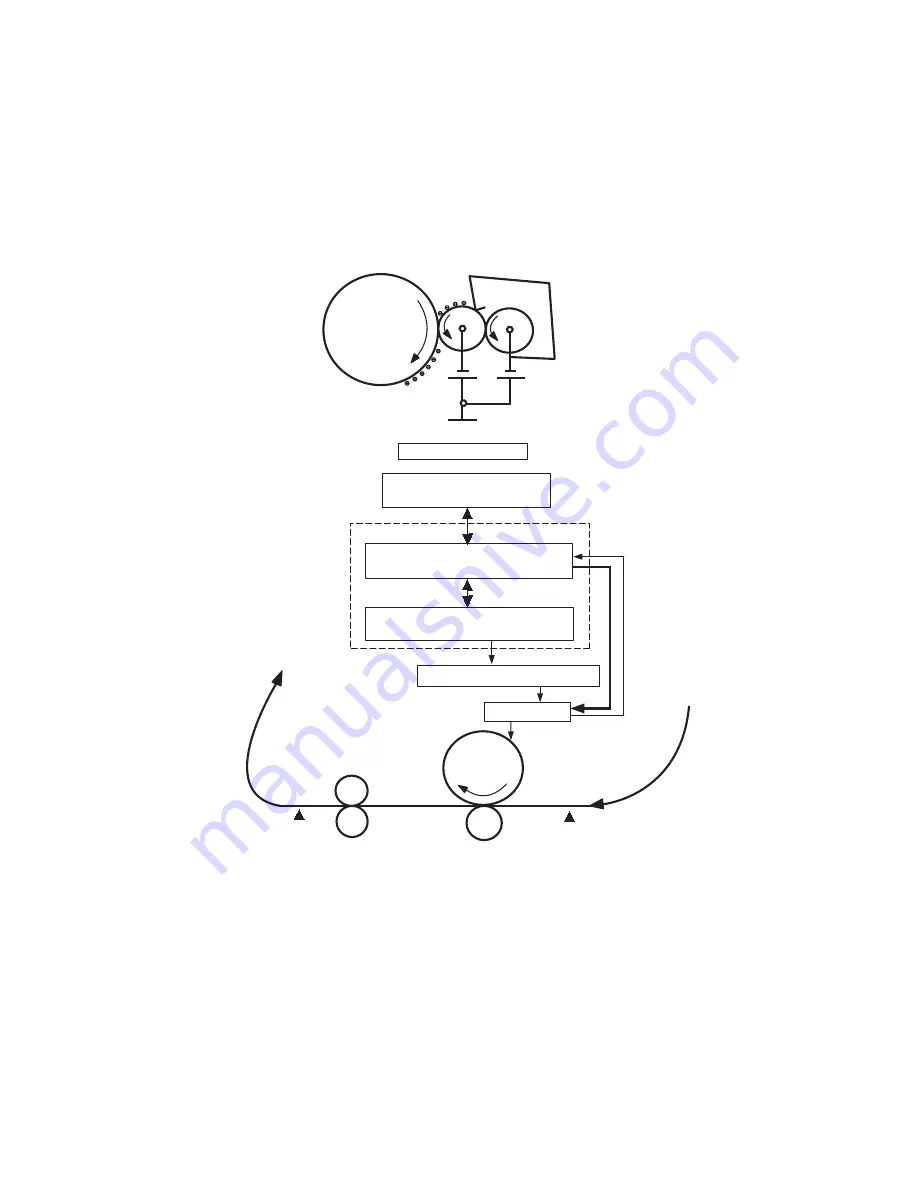
Major Assemblies and Functions
The Phaser 34
25
Laser Printer contains several subsystems. Each subsystem contains
Service Parts identified in the parts list in Chapter 9 of this manual. For information
on repairing or replacing sub-assemblies and Service Parts, refer to the Removal and
Replacement Procedures in Chapter 8 of this manual. Some components may not be
replaceable except as part of a larger component.
Main Board
The Main Board combines the Image Processor and Engine Control functions. It
contains a 266 MHz,
Power PC
processor and comes with a standard memory
capacity of 32 Mbytes. The board provides one expansion slot that allows available
memory to be expanded up to 160 Mbytes by adding an additional 32 Mbyte, 64
Mbyte, or 128 Mbyte DIMM.
.
-
H.V.P.S
LSU
/HSYNC
Host Computer
System Controller
Main Board
Print Engine Controller
Face Down
Stacker
Fuser
Paper
Path
Registration
Sensor
Exit Sensor
Developer
OPC
Metering Blade
-500V
-650V
Develop Block
OPC
D/R
S/R
GND
Summary of Contents for Phaser 3425
Page 1: ...Service Manual P h a s e r L a s e r P r i n t e r 3425 ...
Page 2: ......
Page 14: ...xii Phaser 3425 Laser Printer ...
Page 20: ...xviii Phaser 3425 Laser Printer ...
Page 29: ...General Information 1 9 Consumables 1 Print Cartridge 1 ...
Page 48: ...2 14 Phaser 3425 Laser Printer Service Manual ...
Page 93: ...6 Chapter Adjustments and Calibrations In this chapter Margin Calibration Resetting NVRAM ...
Page 98: ...7 4 Phaser 3425 Laser Printer Service Manual ...
Page 144: ...8 46 Phaser 3425 Laser Printer Service Manual ...
Page 145: ...9 Chapter Parts Lists In this chapter Using the Parts List Print Engine Parts Xerox Supplies ...
Page 175: ...10 6 Phaser 3425 Laser Printer Service Manual ...
Page 179: ......
Page 180: ......


