Troubleshooting
8-2
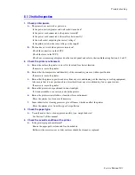
8.1.1 Basic Check List
1.
Check power.
a.
Does
“
Warming Up
”
appear on the display ?
If not, check the power cable, switch or LVPS. (see section 8.1.2 below)
Verify the wall socket outputs the correct voltage.
b.
Do the Motors or other components initialize (listen for the main motor and fan)?
If not, or there is no sounds, check the power cord, switch or LVPS.
Verify the wall socket outputs the correct voltage.
2.
Check the control panel.
a.
Is there anything showing on the control panel display at all?
If not, check the power cord, switch, or LVPS. (see section 8.1.2)
Verify the wall socket outputs the correct voltage.
b.
Is the display clear or cryptic, are there any broken or badly formed characters?
Check the main board and control panel wiring harness.
c.
Is there an error message on the control panel?
Refer to section 8.4 or 8.5.
3.
Check the paper path.
a.
Is there a Paper Jam?
Remove any paper fragments caught in the paper path.
Refer to section 8.3.
b.
Paper Jam occurs repeatedly at a specific point in the paper path.
Check the printers internal paper path and inspect the region where the jam occurs.
Check for paper fragments caught in or around the fuser.
4.
Print a configuration page.
a.
Does the page print?
If there is an error see number 2 or 3 above.
b.
Try printing a test page from a computer.
If there is an error, check cables and driver installation.
5.
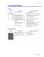
Check the print-quality.
a.
Is there a print quality Problem?
Refer to section 8.2.
6.
Check consumables.
a.
Print a configuration page from the control panel.
Refer to 8.1.4 and to section 3.5 for expected life of various consumable parts, compare this with the figures
printed and replace as required.
Summary of Contents for Phaser 6100
Page 1: ...Service Manual X XEROX P h a s e r C o l o r L a s e r P r i n t e r 6100 ...
Page 2: ......
Page 10: ...vi ...
Page 22: ...Reference Information 2 6 ...
Page 28: ...Specifications 3 6 ...
Page 38: ...Summary of Product 4 10 RAM DIMM SPGPm Main Control FLASH MEMORY ENGINE CONTROL ...
Page 44: ...Summary of Product 4 16 ...
Page 66: ...Disassembly 6 10 3 Remove the toner caps and fit them to the inlets as shown below Toner Cap ...
Page 94: ...Disassembly 6 38 6 Disconnect 2 harnesses and remove the laser unit Harness Harness ...
Page 130: ...Maintenance and Diagnostics 7 20 ...
Page 196: ...Parts List 9 42 9 21 Transfer Belt Cam Assembly S18 9 0 8 S8 7 6 5 10 1 2 14 3 12 13 S8 11 4 ...
Page 200: ...Parts List 9 46 ...


