Summary of Product
Service Manual 4-15
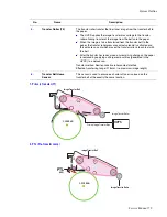
1) Charging Voltage: Charger
■
Function: Charges the surface of the drum to about -500 volt ~ 800 volt.
■
Output voltage: -200 V~-2.0K V DC +/- 3% (Duty is changeable, no loading)
■
Error type: If the correct voltage was not present, the surface of the drum is not charged. As a result, toner
on the developer roller transferred to the drum could produce entirely black prints.
2) Transfer high voltage: T1(+)
■
Function: Used to transfer toner from the drum to the transfer belt.
■
Output voltage: +400 V~ +3.5K V DC +/- 3% (Duty is changeable, no loading)
■
Error type: If the primary transfer voltage was not present, it is not possible to transfer toner from the drum
to the transfer belt. As a result, print output could be faint or blank.
3) Transfer High Voltage: T2 (+)
■
Function: Used to transfer toner from the transfer roller to the paper.
■
Output voltage: +400 V~ +5K VDC +/- 3% (Duty is changeable, no loading)
■
Error type: If the secondary transfer voltage was not present, it is not possible to transfer toner from the
transfer roller to the paper. As a result, print output could be fain or blank.
4) Cleaning voltage: T2 (-)
■
Used in the cleaning process to transfer/clean off the (-) negative toner reamaining on the transfer roller to
the waste toner cartridge.
■
Output voltage: There is no feedback control, and it outputs a fixed voltage (-900V).
■
Error type: Toner contamination occurs on the reverse side of the printed-paper.
5) Supplying voltage: Supply
■
Function: Supply the duplicated (AC+DC) voltage from the HVPS to the DEVE drive board.
■
Output voltage
■
AC Voltage F:1 KHz ~ 3 KHz (Duty is changeable)
■
AC Voltage Vp-p: 1 KV ~ 3 KV
■
DC : -100 V ~ -1000 V
■
Error type: 1. If this voltage is ground, print density is extremely low.
2. If this voltage is floating due to unstable contact points at the HV terminal, density becomes so low as that
printing results appear non-existent.
Summary of Contents for Phaser 6100
Page 1: ...Service Manual X XEROX P h a s e r C o l o r L a s e r P r i n t e r 6100 ...
Page 2: ......
Page 10: ...vi ...
Page 22: ...Reference Information 2 6 ...
Page 28: ...Specifications 3 6 ...
Page 38: ...Summary of Product 4 10 RAM DIMM SPGPm Main Control FLASH MEMORY ENGINE CONTROL ...
Page 44: ...Summary of Product 4 16 ...
Page 66: ...Disassembly 6 10 3 Remove the toner caps and fit them to the inlets as shown below Toner Cap ...
Page 94: ...Disassembly 6 38 6 Disconnect 2 harnesses and remove the laser unit Harness Harness ...
Page 130: ...Maintenance and Diagnostics 7 20 ...
Page 196: ...Parts List 9 42 9 21 Transfer Belt Cam Assembly S18 9 0 8 S8 7 6 5 10 1 2 14 3 12 13 S8 11 4 ...
Page 200: ...Parts List 9 46 ...


