System Outline
5-2
5.1.2 LSU (Exposure)
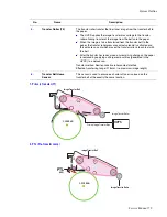
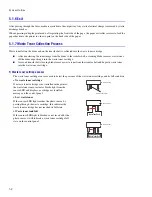
The latent image is formed on the drum using an image data stream to switch the laser beam On or Off. Where no
image is required the beam is off, where toner is required the beam is turned on. When the laser is on and the beam
strikes the drum surface, the charge is reduced to -50 V, where the beam is switched off the charge on the drum
surface remains at -600 V.
5.1.3 Toner Cartridge (Development Section)
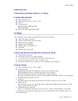
In the development stage, toner particles are transferred from the toner cartridge onto the surface of the drum. The
drum and the developer roller rotate in opposite directions. Toner on the developer roller is charged to the developing
voltage. (see, page 5-7). Toner is attracted to the drum in those areas where the surface charge is -50V. Toner is not
attracted to those areas of the surface carrying a -600 V charge.
1) Type
■
Developing method: Non-magnetic, Mono-component developing system.
■
Toner cartridge order: K, Y, M, C from top.
■
Developing sequence: Y, M, C, K
■
Life span: High Capacity Toner: 7,000 (K) / 5,000 (C, M, Y); Standard: 3000 (K) / 2000 (C,M,Y)
■
Power: DEVE motor (BLDC)
■
Power transmission: Electric clutch
■
Toner remaining: TRC (Toner Reproductive Curve) sensor, +Dot counting method
-600V
-600V
-50V
Reflecting Mirror
Polygon Motor
(30,000rpm)
Unexposed
Exposed
Unexposed
DEV. - Black
DEV. - Yellow
DEV. - Magenta
DEV. - Cyan
DEV. - Black
DEV. - Yellow
DEV. - Magenta
DEV. - Cyan
OPC
Drum
Drum
Drum
Dev Roller
Developing
Voltage
Dev Gap
Summary of Contents for Phaser 6100
Page 1: ...Service Manual X XEROX P h a s e r C o l o r L a s e r P r i n t e r 6100 ...
Page 2: ......
Page 10: ...vi ...
Page 22: ...Reference Information 2 6 ...
Page 28: ...Specifications 3 6 ...
Page 38: ...Summary of Product 4 10 RAM DIMM SPGPm Main Control FLASH MEMORY ENGINE CONTROL ...
Page 44: ...Summary of Product 4 16 ...
Page 66: ...Disassembly 6 10 3 Remove the toner caps and fit them to the inlets as shown below Toner Cap ...
Page 94: ...Disassembly 6 38 6 Disconnect 2 harnesses and remove the laser unit Harness Harness ...
Page 130: ...Maintenance and Diagnostics 7 20 ...
Page 196: ...Parts List 9 42 9 21 Transfer Belt Cam Assembly S18 9 0 8 S8 7 6 5 10 1 2 14 3 12 13 S8 11 4 ...
Page 200: ...Parts List 9 46 ...


